
Cisco IOS Switching Services Configuration Guide, Release 12.2 - Routing Between VLANs Overview [Cisco IOS Software Releases 12.2 Mainline] Routing Between VLANs Overview This chapter provides an overview of VLANs.
![Cisco IOS Switching Services Configuration Guide, Release 12.2 - Routing Between VLANs Overview [Cisco IOS Software Releases 12.2 Mainline]](http://cdn.pearltrees.com/s/pic/th/switching-configuration-93730929)
It describes the encapsulation protocols used for routing between VLANs and provides some basic information about designing VLANs. This chapter describes VLANs. It contains the following sections: Layer 3 versus Layer 2 Switch for VLANs - Cisco Meraki KB - Meraki Dashboard. This article discusses the difference between layer 2 and layer 3 switches and the appropriate use cases for each.
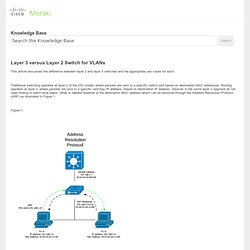
Traditional switching operates at layer 2 of the OSI model, where packets are sent to a specific switch port based on destination MAC addresses. Routing operates at layer 3, where packets are sent to a specific next-hop IP address, based on destination IP address. Devices in the same layer 2 segment do not need routing to reach local peers. What is needed however is the destination MAC address which can be resolved through the Address Resolution Protocol (ARP) as illustrated in Figure 1. Multiple VLAN on one cisco port switch. Cisco Nexus 5000 Series NX-OS Software Configuration Guide - Configuring VLANs [Cisco Nexus 5000 Series Switches] Configuring VLANs You can use virtual LANs (VLANs) to divide the network into separate logical areas.
![Cisco Nexus 5000 Series NX-OS Software Configuration Guide - Configuring VLANs [Cisco Nexus 5000 Series Switches]](http://cdn.pearltrees.com/s/pic/th/configuration-configuring-93730574)
VLANs can also be considered as broadcast domains. Any switch port can belong to a VLAN, and unicast, broadcast, and multicast packets are forwarded and flooded only to end stations in that VLAN. Each VLAN is considered a logical network, and packets destined for stations that do not belong to the VLAN must be forwarded through a router. This chapter includes the following sections: Information About VLANs This section includes the following topics: Understanding VLANs Note VLAN Trunking Protocol (VTP) mode is OFF.
A VLAN is a group of end stations in a switched network that is logically segmented by function, project team, or application, without regard to the physical locations of the users. Any port can belong to a VLAN, and unicast, broadcast, and multicast packets are forwarded and flooded only to end stations in that VLAN. How to Create VLAN Trunking on Cisco Catalyst Switch. If you have multiple switches that are part of a stack, then any VLAN you create on the master switch is available on all the switches in the stack.
However, if you have multiple switches that are not part of stack, and if you need to use the same VLAN between these two switches, you need to use VLAN trunking. This tutorial explains how to configure VLAN trunking between two different switches. 1. Connect the Switches First, to use VLAN trunking, you need to physically connect the switches using ethernet cable. Switch1:port24 —> Switch2:port24 Depending on your bandwidth requirement, you can choose to even use two ports for VLAN trunking. i.e You can use both port23 and port24 connected between Switch1 and Switch2 using two ethernet cables. 2.
In this case, let us assume that you have a VLAN 140 on Switch1, which you can trunk on Switch2 also. Login to Switch1, and specify the spanning-treen on this particular VLAN 140 as shown below. switch1(config)# spanning-tree vlan 140 root primary. Connecting two VLANs together on a single switch - Network Engineering Stack Exchange. I'm doing some experiments and I want to know if it is possible to connect two VLANs on a single switch by using just a cable between one group of ports and the other.
My goal is to simulate (using only one physical switch) two independent switches connected together by a fiber cable. I'm using per-port based VLANs and my current setup is: VLAN 1: ports 1-24,49 VLAN 2: ports 25-48,50 I want to connect these VLANs using a cable from port 49 to port 50. Both of these VLANs are supposed to be in the subnet 10.128.0.0/24. Connecting the cable didn't work. [update] I'm sorry if I have not made myself clear. The switch is an Arista 7048T-A.
When I say it didn't work, I mean that a computer on VLAN 1 can't ping a computer on VLAN 2, even though those VLANs are connected to each other through a cable. My understanding was that creating VLANs would effectively separate the address learning of the ports, but according to mellowd's answer, I was wrong. Following the question: If yes, how? LAN, Switching and Routing. Switches & Bridges (Networking)