
Ringing (signal) This article is about ringing in electronics and signals generally.
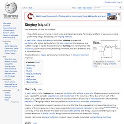
For ringing artifacts in signal processing, particularly image processing, see ringing artifacts. Ringing is undesirable because it causes extra current to flow, thereby wasting energy and causing extra heating of the components; it can cause unwanted electromagnetic radiation to be emitted[citation needed]; it can delay arrival at a desired final state (increase settling time); and it may cause unwanted triggering of bistable elements in digital circuits. Ringy communications circuits may suffer falsing. Ringing can be due to signal reflection, in which case it may be minimized by impedance matching. Ringing can affect audio equipment in a number of ways. Transducers (i.e., microphones and loudspeakers) can also ring. In digital audio, ringing can occur as a result of filters such as brickwall filters. Ringing (signal) Clipping (signal processing) An oscilloscope screen of an amplifier "clipping.
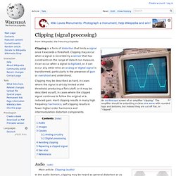
" The amplifier should be outputting a clean sine wave with rounded tops and bottoms, but instead they are cut off flat, or "clipped". Clipping may be described as hard, in cases where the signal is strictly limited at the threshold, producing a flat cutoff; or it may be described as soft, in cases where the clipped signal continues to follow the original at a reduced gain. Hard clipping results in many high frequency harmonics; soft clipping results in fewer higher order harmonics and intermodulation distortion components. Sinc filter. It is an "ideal" low-pass filter in the frequency sense, perfectly passing low frequencies, perfectly cutting high frequencies; and thus may be considered to be a brick-wall filter.
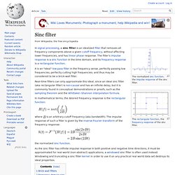
Real-time filters can only approximate this ideal, since an ideal sinc filter (aka rectangular filter) is non-causal and has an infinite delay, but it is commonly found in conceptual demonstrations or proofs, such as the sampling theorem and the Whittaker–Shannon interpolation formula. In mathematical terms, the desired frequency response is the rectangular function:
Ringing artifacts. Image showing ringing artifacts. 3 levels on each side of transition: overshoot, first ring, and (faint) second ring.
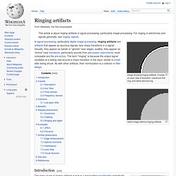
Same image without ringing artifacts. Introduction[edit] Gibbs phenomenon. In mathematics, the Gibbs phenomenon, discovered by Henry Wilbraham (1848)[1] and rediscovered by J.
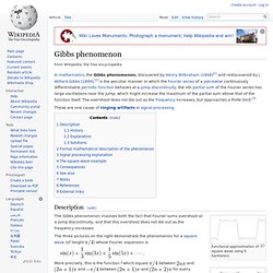
Willard Gibbs (1899),[2] is the peculiar manner in which the Fourier series of a piecewise continuously differentiable periodic function behaves at a jump discontinuity: the nth partial sum of the Fourier series has large oscillations near the jump, which might increase the maximum of the partial sum above that of the function itself. The overshoot does not die out as the frequency increases, but approaches a finite limit.[3]
Step response. From a practical standpoint, knowing how the system responds to a sudden input is important because large and possibly fast deviations from the long term steady state may have extreme effects on the component itself and on other portions of the overall system dependent on this component.
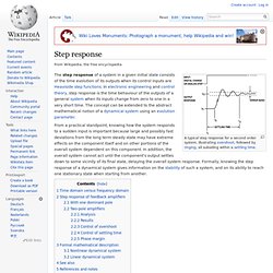
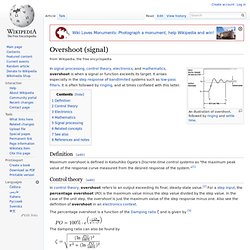
In addition, the overall system cannot act until the component's output settles down to some vicinity of its final state, delaying the overall system response. Formally, knowing the step response of a dynamical system gives information on the stability of such a system, and on its ability to reach one stationary state when starting from another. Time domain versus frequency domain[edit] Instead of frequency response, system performance may be specified in terms of parameters describing time-dependence of response. Overshoot (signal) Maximum overshoot is defined in Katsuhiko Ogata's Discrete-time control systems as "the maximum peak value of the response curve measured from the desired response of the system.
Inrush current limiter. An inrush current limiter is a component used to limit inrush current to avoid gradual damage to components and avoid tripping the supply's fuse or circuit breaker.
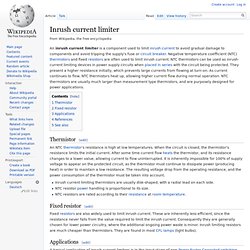
Negative temperature coefficient (NTC) thermistors and fixed resistors are often used to limit inrush current. NTC thermistors can be used as inrush-current limiting devices in power supply circuits when placed in series with the circuit being protected. They present a higher resistance initially, which prevents large currents from flowing at turn-on. As current continues to flow, NTC thermistors heat up, allowing higher current flow during normal operation. NTC thermistors are usually much larger than measurement type thermistors, and are purposely designed for power applications.
Thermistor[edit] Inrush Current FAQs. Passive or Active Protection for Inrush Current?

There are several component options for inrush current limiting. The two most common alternatives are the use of NTC (Negative Temperature Coefficient) thermistors or various forms of active circuits. However, the most appropriate inrush current suppression technique for a particular application depends on component pricing issues, the equipment's power level, and the frequency at which the equipment is likely to be exposed to inrush currents. No single component solution can be best for every application.
Each approach has its own advantages and disadvantages. Inrush current. An example of inrush current transients during capacitor bank energization.
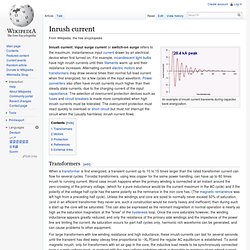
Transformers[edit] When a transformer is first energized, a transient current up to 10 to 15 times larger than the rated transformer current can flow for several cycles. Toroidal transformers, using less copper for the same power handling, can have up to 60 times inrush to running current. Inrush current.