
Code, circuits, & construction. A stepper motor is a motor controlled by a series of electromagnetic coils.
The center shaft has a series of magnets mounted on it, and the coils surrounding the shaft are alternately given current or not, creating magnetic fields which repulse or attract the magnets on the shaft, causing the motor to rotate. This design allows for very precise control of the motor: by proper pulsing, it can be turned in very accurate steps of set degree increments (for example, two-degree increments, half-degree increments, etc.). They are used in printers, disk drives, and other devices where precise positioning of the motor is necessary. There are two basic types of stepper motors, unipolar steppers and bipolar steppers. Unipolar Stepper Motors The unipolar stepper motor has five or six wires and four coils (actually two coils divided by center connections on each coil).
Bipolar stepper motors The bipolar stepper motor usually has four wires coming out of it. Two-Wire Control. All-Terrain Electric Scooter. As seems to be the case with many of my projects, for this one, I acquired the parts first, and then designed a project to fit the parts I had.

Here is the back story of how I got the parts, and what drove me to use them to build the vehicular monstrosity this post is about. But first, a brief overview of the scooter's specs:Motors: 3x CIM motorsBatteries: 8x Turnigy 5000 mAh 4s LiPo packs, 16s2p configuration (59.2V, 10 Ah)Controller: Kelly KDS72200E, 72V, 120 A continuous, 200A peakWheels: 12.5" with knobby pneumatic tiresDeck: Hand laminated carbon fiber with polycarbonate topFrame: Royce Union Transit kick scooter, with about 200% more aluminum addedBrake: Pedal actuated rear disk (sprocket) brakeVideos are at the bottom of the post. At the beginning of this past school year, my school's robotics team decided to finally dismantle some old FRC robots that had been collecting dust for six or seven years. Front suspension. Transistor LED Flasher - Jose Pino's Projects and Tidbits.
If you are familiar with LED flashers using transistor, you may know the basic one uses two transistor, one capacitor and three resistors.
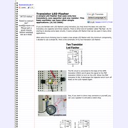
There is other kind of oscillator called "flip-flop". As I'm starting to develop some basic circuits, I need a simple LED flasher that can be used in many other applications. After some hours thinking how to create a new simple LED flasher with the minimum components, I decided to use a simple RC. Circuit Skills: Circuit Board Etching. Networked Arduino Heartbeat sensor + SuperCollider. I made a simple heartbeat sensor using an Arduino which sends OSC signals at each heartbeat over a network.
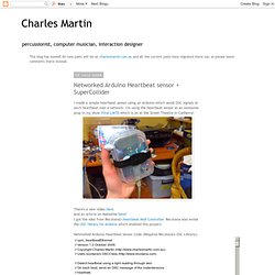
I'm using the heartbeat sensor as an awesome prop in my show .. Recotana also wrote the which enabled this project. // cpm_heartbeatEthernet // Version 1.0 October 2009. // Copyright Charles Martin ( // Uses recotana's OSCClass ( // Detect heartbeat using a light reading through skin // On each beat, send an OSC message of the instantaneous // heartrate.
#include "Ethernet.h" #include "OSCClass.h" // Pins const int ledPin = 13; const int sensePin = 0; Pulse Oximetry. Principles of Pulse Oximetry Technology: The principle of pulse oximetry is based on the red and infrared light absorption characteristics of oxygenated and deoxygenated hemoglobin.
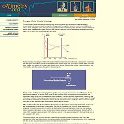
Oxygenated hemoglobin absorbs more infrared light and allows more red light to pass through. Deoxygenated (or reduced) hemoglobin absorbs more red light and allows more infrared light to pass through. Red light is in the 600-750 nm wavelength light band. Infrared light is in the 850-1000 nm wavelength light band.
Still alive? heartbeat (IR)sensor report. Principles: Sense heart rate by using a pair of infrared emitter and reciever, next to each other on top the measuring site on top of the finger.
The light bounces from the emitter to the detector across the site. with each heart beat the heart contracts and there is a surge of arterial blood, which momentarily increases arterial blood volume across the measuring site. Collin's Lab: Infrared heart sensor. After checking out a few projects involving IR heart monitors, I decided to have a go at the interface myself.
Collin's Lab: Infrared heart sensor. How to make an infrared heart sensor. Create your own messages. ELECTRONICS - THE KING OF HOBBIES!: Scrolling text in LED dotmatrix display. Multiplexed displays are electronic displays where the entire display is not driven at one time.
Instead, sub-units of the display (typically, rows or columns for a dot matrix display or individual characters for a character orientated display, occasionally individual display elements) are multiplexed, that is, driven one at a time, but the electronics and the persistence of vision combine to make the viewer believe the entire display is continuously active. Avr PID controller. DS1307 RTC tutorial.
Begin assembly. Cheap and Easy Time Lapse Video (Intervalometry) Time lapse, also known as intervalometry (as in measuring intervals between photographs), is a method of taking pictures slowly over time and then compiling them into a video of compressed time.
I've always been fascinated with time lapse videos. QUANTSUFF's LED-boost Pages - Page 1. Assembly. Fire it up!