
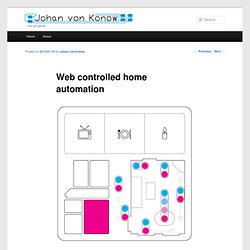
Web controlled home automation. Description This post is the last of three and describes the software needed to build a web controlled home automation center.
The previous two describes how to add a serial interface to a router and how to build a microprocessor lab board. Features Software for the router (OpenWrt)Software for the web server (html and CGI)Software for the lab board (PIC16F628 assembler)Protocol for serial communication between router and lab boardProtocol for 433MHz radio (and html generation tools) Development My first project for the web access lab board is an Internet controlled home automation system. In a way using a separate microprocessor for the radio communication is overkill. This is how it works: Installing the router It was very easy to install and set up OpenWrt on the router (by following the steps in this link The biggest problem was to change the baud rate on the serial port.
Setting up the web interface I wanted to have a visual control over all the lights in my apartment. Irrigating your garden with an opamp: Improvements, expansions, winter use. Picture 1 The first picture shows my (still experimental) set up: The white wire is the sensor. the thin red and black are the power supply that (for now) feeds from a 12 Volt rail for my garden lights.
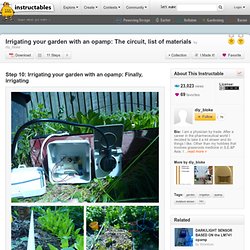
The level switch feeds in the same connector block as the sensor does. The thick black and blue leads (lower right) form the switched supply to the wall socket to the right. Currently they all exit via one hole, which is probably not according to Code, but I will fix that eventually as for now I am not sure yet if I will leave the opamp circuit outside, or will bring it in the house eventually. Actually according to local Code I should have used a brown thick wire instead of a blue one but who is gonna know? The plug in the wall socket is the plug of my pump. Picture 2 There are several ways to deliver the water to your plantbed such as a drip system or a soaker hose. In the picture you wil also see some moisture sensors (I have tested a few, only one is connected). Monitoring Power Consumption with the ACS715. We needed a power meter for monitoring power consumption of our ham radio's when in emergency communications mode (no grid).
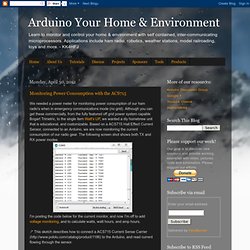
Although you can get these commercially, from the fully featured off grid power system capable Bogart Trimetric, to the single item Watt's UP, we wanted a diy homebrew unit that is educational, and customizable. Based on a ACS715 Hall Effect Current Sensor, connected to an Arduino, we are now monitoring the current consumption of our radio gear. The following screen shot shows both TX and RX power modes. I'm posting the code below for the current monitor, and now I'm off to add voltage monitoring, and to calculate watts, watt hours, and amp hours. /* This sketch describes how to connect a ACS715 Current Sense Carrier ( to the Arduino, and read current flowing through the sensor.