
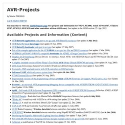
Fjenett/Guido. Using Maxim DS1307 Real Time Clock with Atmel AVR Microcontroller. Using Maxim DS1307 Real Time Clock with Atmel AVR Microcontroller May 11, 2009 by rwb, under Microcontroller.
Building our own digital clock is one of the dreamed project by most of the hobbyist or anyone that want to learn or involve seriously in the embedded system world; the ability to integrate time, day and date to the embedded system is one of the important knowledge that should be known by any embedded system designer. Today’s technology makes life easier as all these capabilities has already built nicely inside the Maxim (Dallas) DS1307 Real Time Clock (RTC) chip. Learning to use the V-USB (AVR USB firmware) library. Programming AVR I2C interface. I2C (also referred as IIC or TWI) is widely used interface in embedded applications.
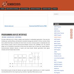
Two wire bus initially was used by Philips and become a standard among chip vendors. I2C bus consists of two lines called Serial Data Line (SDA) and Serial Clock Line (SCL). Communication is relatively fast and short distance mainly used to communicate between sensors, RTC, EEPROM, LCD. I2C protocol allows up to 128 devices connected to those two lines where each of them has unique address. RTC1307 - Real Time Clock - Combustory. From Combustory Welcome to Combustory Any questions or comments: Send them to - combustor@combustory.com Summary This code shows how to communicate with the RTC DS1307 Real Time Clock, which is used to set and retrieve the date/time of the chip. Note of gratitude to Maurice Ribble - for the majority of the RTC DS1307 code. Four Walled Cubicle - AVR Articles.
Pwm based power control : 8051 Microcontroller Projects AVR PIC Projects Tutorials Ebooks Libraries codes. Phil Give you very nice info....... now its time to try this do it in practical...make its hardware it will work,,,,,, you need a zero crossing detector.......
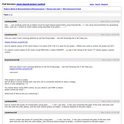
Why you need this??? I hope u are familiar with firing angel of TRIAC.. when u give pulse on its Gate from Controller it turns ON....... now how much time it remains ON??? It depends on what is frequency of your applied voltage for example if u are using it at 220v, 50Hz or 50 c/s and you set firing angel at 0 degree..... it means TRIAC will be ON from 0 degree to 180 Degree for Positive Half cycle and 180 Degree to 360 Degree for Negative Half Cycle..... and total time can be calculated by this formula time= 1/frequency....... so in this case time= 1/50.....that is 0.02 seconds..... so.
WinAVR AVR-GCC Tutorial. The Universal Synchronous and Asynchronous serial Receiver and Transmitter (USAR) is powerful and useful interface in many projects.
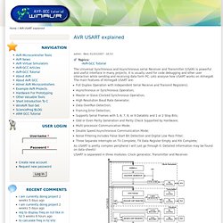
It is usually used for code debugging and other user interaction while sending and receiving data form PC. Lets analyse how USART works on Atmega8. Running TX433 and RX433 RF modules with AVR microcontrollers. Sometimes in embedded design you may want to go wireless. Might be you will want to log various readings of remotely placed sensors, or simply build a remote control for robot or car alarm system. Nokia 3310/5110 LCD tutorial (PCD8544)
Design with Microcontrollers: NOKIA 3310 LCD interfacing with ATmega8. Hi friends, using graphic LCD in a project gives itreally a good look and flexibility of displaying different characters and shapes.

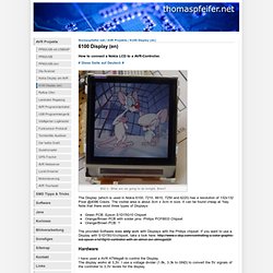
But, the graphic LCDs are quite costly. The NOKIA 3310 LCD provides a really low-cost solution to add a small graphic display into your project and also good for learning purpose. The LCD is SPI bus compatible, saving many pins for other uses. It operates at 3.3v. Controlling a Nokia 6100 Display with an Atmel-AVR. Thomaspfeifer.net / AVR Projekte / 6100 Display (en) How to connect a Nokia LCD to a AVR-Controller. # Diese Seite auf Deutsch # The Display (which is used in Nokia 6100, 7210, 6610, 7250 and 6220) has a resolution of 132x132 Pixel @4096 Colors.
C-o-r-E/AVR-MIDI-Player. BTc Sound Encoder v3.0 - free sound software. .BTL file loads direct into hardware and contains multiple sounds (so the hardware can automatically play any sound) Library Files are a powerful feature that many people have asked for. You can join your sound WAVs together to make one neat easy file, and BTc Sound Encoder v3.0 handles the tricky bits like the sound Start and End pointers needed to play each sound. Then you can export the .SL Sound Library as a .BTL (BTc Library) which is one easy file to be loaded directly into your hardware. The hardware then has everything is needs to automatically "play sound1" or "play sound2" etc.
Sound pointers are automatically placed when you add new sounds to the sound library. How to Play sound with a singel chip AVR - Sonsivri. Avrprog / AvrSound. Using the term 'music' liberally here, it will play a squeaky, but recognizable stream of audio, generated from MIDI files.
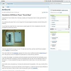
It's a satisfying little project that is a nice change from the typical beginner embedded controller blinking LED project(s). You can't get any simpler than this: a piezo buzzer, a power supply (3x1.5 AA), a breadboard, and an AVR (ATmega16, but almost any will do). You'll also need WinAVR or avr-gcc on Linux. To make new music files, you'll also need Perl and a program such as MIDICSV to convert the files. This code is lifted from the AvrButterfly originally from Atmel, and as modified and ported by MartinThomas to GCC. I've made a few changes. Once loaded, wired, and powered up, it will play the selected audio file repeatedly.
I'm still learning how to use the clock prescaler on the ATmega16, so I made life simple and used AVRStudio to adjust the clock down to 1MHz to make it match the prescaled value from AvrButterfly MIDI File Conversion avrsound.zip archive. Contact. AVR projects and AVR Butterfly gcc port. By Martin THOMAS G.d.W.
SS2010 FHFFM. AVR Tutorial - Fuses. AVR TutorialFuses ladyada.net Fuses are an extremely important part programming a chip, but are rarely explained thoroughly.
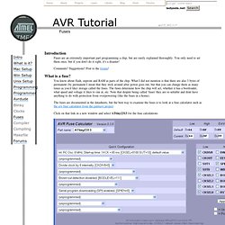
You only need to set them once, but if you don't do it right, it's a disaster! Comments? Suggestions? You know about flash, eeprom and RAM as parts of the chip. The fuses are documented in the datasheets, but the best way to examine the fuses is to look at a fuse calculator such as the avr fuse calculator from the palmavr project Click on that link in a new window and select ATtiny2313 for the fuse calculations We'll use the Quick Configuration so use those menus, not the checkboxes The first option is how the chip is clocked. AVR Fuse Calculator.
Uhttpd-avr - micro HTTPD server based on modified uIP-1.0 stack, running on 8bit AVR processor and ENC28J60. Power Manager. ENC28J60 Ethernet Chip Driver Module This module is composed of exactly two header files and a source file.
The purpose of this module is to define and implement all of the driver functions that are necessary to transmit and receive data packets from the local area network. The enc28j60.h header file defines different pin configurations for the board where the chip is located.The driver abstracts away all of the complicated SPI communication between the MCU and the ENC28J60 board from other components that make up PowerManager. This makes writing and receiving packets into a matter of a few simple function calls. The enc28j60def.h header file defines all of the memory locations for the different bank registers, register bits, and SPI operation codes for the ethernet controller.
Network Interface Card (NIC) Module This module further simplifies the process of sending and receiving packets by abstracting away the ethernet driver details. DHCPC Module uIP Module. [TUT][C] LCD Tutorial 1001. Tutorial for HD44780-LCD and similar. Following an easy, universal and code saving example. 1. There are different ways to control the LCD. You can use the 8bit mode with busy testing or the 4bit mode with busy waiting. [TUT] [C] Newbie's Guide to AVR Timers. For an updated version of this tutorial in PDF format, please see this page of my website.
Newbie's Guide to AVR Timers(C) Dean Camera, 2007 At last! Yet another tutorial, this one covering a topic which is the main source of frustration to those new with AVRs; timers.