
eCalc - xcopterCalc - the most reliable RC Calculator on the Web. Autopilota : VR Micro Brain 5.1.
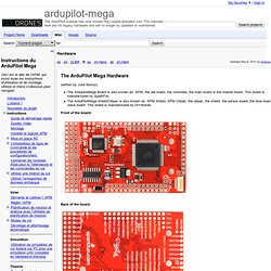
Gimbal. Sensors. Hardware - ardupilot-mega - Official ArduPlane repository. The ArduPilot Mega Hardware (written by Jordi Munoz) The ArdupilotMega Board is also known as: APM, the red board, the controller, the main board or the master board.
IMUHardware - ardupilot-mega - Official ArduPlane repository. The ArduPilot Mega IMU shield Hardware The two expansion ports go to ATmega1280 pins PF6 and PF7.
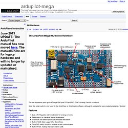
That's Analog 5 and 6 in Arduino. Note: the slider switch is not used by the ArduPlane or ArduCopter software, although it available for user-created programs if desired. Features Dual 3.3V Regulator. PCB files IMU shield Eagle files: USB Remote. Using just an inexpensive push button switch, a converted USB cable, and a small battery, you can construct a remote device that will allow you to control the operation of your CHDK-enabled camera.
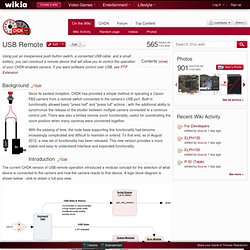
If you want software control over USB, see PTP Extension Background Edit Since its earliest inception, CHDK has provided a simple method of operating a Canon P&S camera from a remote switch connected to the camera's USB port. Built-in functionality allowed basic "press half" and "press full" actions - with the additional ability to synchronize the release of the shutter between multiple camera connected to a common control unit.
Ardu_control_station.
Link_fibra carbonio. Kalman filter. Vuzix VR920 API Integration. Circularly Polarized Helical antenna 7.5 -13 dbi - New: Wave Trap match! Choose only one method described here.
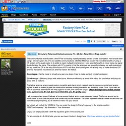
Use whatever method appears easiest as they all work. Your helix is almost done. Now to match it. DIY 5.8GHz Helix. D.I.Y. 2.4GHz Helical Antenna. This is a sligh rehash of the original article from 1999.
It's still useful as a guide though some of the shops probably don't exist any more and if you look around the WWW you will find variations of this design. As some of the readers may know, an effort by members of the Canberra Linux Users Group has been launched to set up a Canberra-wide wireless LAN. This amateur experiment's existence is largely due to the acquisition of many cut-price old style Lucent WaveLAN cards being superseded by the IEEE 802.11 standard cards.
The cards were cheap but the tile antennas that came with them are no good for long haul links of more than several hundred metres. On top of this, commercial aerials that can do the job are expensive, can get rather large and are ugly, especially the conifers. Yet Another Newbie 5.8GHz Setup - A Catalog of Statics - Page 3. Quote: Your are not hijacking, I am really happy if my (very) little experience can be useful to someone.

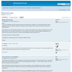
I am using this picture for the channel selection: For the detailed explanation of why the switches are like this you can have a look at sammyc link a few posts back. I did not really do my antenna for a specific channel I just used 5.8GHz as the target which is in the middle of the band.
NANOcopters. PxaRC - R/C and robotics software for Linux/PXA255/PXA270. Arduino. Spacenav web site. VTK/3DConnexion Devices Support. View topic - Can SpaceNavigator be used in embedded application? 3DConnexion with USB Host Shield 2.0 · Issue #19 · felis/USB_Host_Shield_2.0. View topic - Robotic Arm Control via Embedded System MCU. /* Randy Westlund * Space Navigator Project * 7/24/12 * * This program is designed to parse the HID stream from the space navigator and * convert it to serial commands, which can be sent to a maple.
In this way, I * will demonstrate control of an arm with the space navigator prior to moving * it to an embedded system. *//* NOTE: link with -lpthread to print errno from gdb */ #include <stdio.h> int main(int argc, char **argv){ int x, y, z, rx, ry, rz; /* position and rotation */ /* PACKET PROTOCOL * The space navigator sends packets over the HID stream.
If the stick is not * at rest, position packets are sent at 60Hz. While(1) { unsigned char readbuff[14]; /* max packet size = 14 */ *readbuff = fgetc(infile); /* read the first char of the packet */ switch(*readbuff) { case 0x01: /* position/rotation packet */ fread(readbuff+1, sizeof(char), 13, infile); /* read rest of packet */ View topic - Really direct input. I investigate the same subject.
It is not necessary to find out how the controller works electronically, nor is it too hard to figure it out if you open one. (I guess it does not feed analogue signals through a ... USB for obvious reasons, but has 6 DOF A/Ds feeding a CoTS serial device). (theoretically you could use a polling A/D for all six axes, instead of 6, since, regardless of how you scan -parallel or serial, you feed a serial device.