
Tools, Parts, Kits for DIY'ers - Curious Inventor. LPC-P1114 - OLIMEX - BOARD, DEV, ARM, NXP, LPC1111. Savage Circuits - Mixed Voltage Systems: Interfacing 5V and 3.3V Devices.
Dream Green House. Monosx. Nyák Iroda BT. - Nyák gyártás, kivitelezés. Nyomtatott áramkör tevezés. Making PCBs. How to make really really good homemade PCBs Note - this article is original material.

There is currently a plagiarised copy of it on the site of an Indian electronics magazine credited to a rip-off artist called Indrani Bose. This page is a guide to producing consistently high quality PCBs quickly and efficiently, particularly for professional prototyping of production boards. Unlike most other PCB homebrew guides, emphasis is placed on quality, speed and repeatability rather than minimum materials cost, although the time saved by getting good PCBs every time usually saves money in the long run - even for the hobbyist, the cost of ruined PCB laminates can soon mount up! With the methods described, you can produce repeatably good single and double-sided PCBs for through-hole and surface mount designs with track densities of 40-50 tracks per inch and 0.5mm SMD pitches. Artwork generation When defining pad and line shapes, the following minimum sizes are recommended for reliable results: Media.
DS2408 circuit , 21. DS2408 AS PARASITE-POWERED PUSH-BUTTON SENSOR Application Schematic. Www.epanorama.net/sff/Digital/Interfaces/Extend Ratings of One Wire Swirches.pdf. 1-wire lamp control. Status: Fully working This is a project which connect a Maxim/Dallas Semiconductor microlan to a computer.

The goal is to let the computer check if there's daylight in the apartment, and if there isn't some bulbs will be turned on. Schematics: PC Interface - DS2480B Relay circuit - 1 channel, DS2405 Relay circuit - 2 channels, DS2406 Testcircuit (which also measure light) - DS2450 Measure temperature - DS1820 Led-controller - DS2405 with Mos-Fet Pressure sensor MPXA4115 Pictures: Picture of DS2405&Mos-Fet with 10mm white led DSS2450 4-input A/D with resistor and an LDR.
DS2450 & LDR covered in schrinktube. Another picture of DS2405&Mos-Fet with 10mm white led, even smaller this time! Scripts: The first script runs every hour and checks what time it is. . #! Script #2: This script reads the values from a 2450's A/D's and logs them to a file. . #! Www.kaiturn.com. 5pair IDC connecting block for 110 blocks - 110 Wiring Blocks - Reachup Electronic Technology Co,.Ltd.
Do I really need a transistor to drive my solid state relay? - Hardware. Mdesmarais, on Feb 20 2010, 07:14 AM, said: morglum, on Feb 20 2010, 01:36 AM, said: Just to make sure, just replacing the LED with my relay and the 330 ohm resistor with a 1000 ohm resistor doesnt sound like a really bad idea, correct?
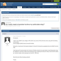
Also, quick newbie question if you don't mind. What's a good way to connect my DS2413? There's no way I could just solder wire to those small legs.... should I get a PCB? 1st question- You can calculate the current- I=E/R. . . so if you are using 5V, current would be 5/1000 = 5mA. BLH, on Feb 20 2010, 07:39 AM, said: I looked at the DS2413 specifications sheet and it is only available in surface mount. Thanks guy for your help. 1) For the resistor/amp calculation, I think I understand. 2) Re: the DS2413.
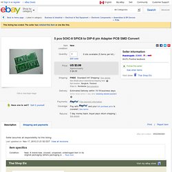
Thanks! 5 pcs SOIC-8 SPIC8 to DIP-8 pin Adapter PCB SMD Convert. Shipping to: Worldwide.
Voltage Sensor Module -Arduino Compatible - emartee.com. Arduino Voltage Sensor Module Description : This module is based on resistance points pressure principle, and it can make the input voltage of red terminal reduce 5 times of original voltage.
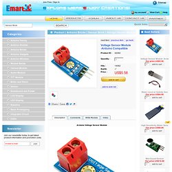
The max Arduino analog input voltage is 5 V, so the input voltage of this module should be not more than 5 V x 5 = 25 V ( if for 3.3 V system, the input voltage should be not more than 3.3 V x 5 = 16.5 V ). Because the Arduino AVR chip have 10 bit AD, so this module simulation resolution is 0.00489 V (5 V / 1023), and the input voltage of this module should be more than 0.00489 V x 5 = 0.02445 V.
Special Parameters :