
Bluetooth Shield. Bluetooth Shield From Wiki 来自痴汉的爱 Jump to: navigation, search The first game operated by goldceo.
Théorie - Relais. Electronique > Théorie > Relais Dernière mise à jour : 06/07/2014 Présentation Un relais est un appareil dans lequel un phénomène électrique (courant ou tension) contrôle la commutation On / Off d'un élement mécanique (on se trouve alors en présence d'une relais électromécanique) ou d'un élement électronique (on a alors affaire à un relais statique).
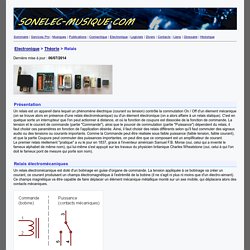
C'est en quelque sorte un interrupteur que l'on peut actionner à distance, et où la fonction de coupure est dissociée de la fonction de commande. La tension et le courant de commande (partie "Commande"), ainsi que le pouvoir de commutation (partie "Puissance") dépendent du relais, il faut choisir ces paramètres en fonction de l'application désirée.
How to connect Arduino and RFID. Moving Forward with Arduino – Chapter 15 – RFID Introduction. Learn how to use RFID readers with your Arduino. In this instalment we use an RDM630 or RDM6300 RFID reader. If you have an Innovations ID-12 or ID-20 RFID reader, we have a different tutorial for you. PRFID. Commandez vos prises électriques avec Arduino » Gr4nth.
Dans cet article je souhaite vous faire découvrir la librairie RC-Switch . Lecture de badge RFID avec Arduino » Gr4nth. Pour mon projet j’ai besoin d’établir un moyen de contrôler l’accès.
Après avoir envisagé plusieurs solutions j’ai finalement décidé de me tourner vers un lecteur RFID 125Khz capable de lire tout type de badges à base de UEM4100. Vous verrez dans cet article qu’il n’est pas très compliqué d’utiliser ce type de lecteur avec une carte Arduino. Cependant, attention, car les instructions qui suivent ne sont valables que pour un lecteur RFID compatible avec le format Wiegand .
Je vous conseille vivement de vous procurer celui de Seeedstudio. Vous le trouverez en France chez le distributeur Evola . Voici maintenant un exemple basique d’utilisation qui vous permettra de partir sur de bonnes bases. Le matériel. Jcw/ethercard. Arduino + ENC28J60 Ethernet Module - Part 2. So at the end of my last adventure with the ENC28J60 and my Arduino Uno I got it working with the 0021 IDE (so I expect it will work with 0022 and 0023 but I have not tested) and the nuelectronics.com library available from here using the following wiring to an Uno.
VCC - 3.3V GND - GND SCK - Pin 13 SO - Pin 12 SI - Pin 11 CS - Pin 10 After my success with this I thought I'd try it with IDE 1.0 and it failed. The nuelectronics library for the ENC28J60 does not work (as of writing) with IDE 1.0. After a little more hunting I found the ethercard library that works with IDE 1.0. I loaded up the backSoon web server sketch that even uses DHCP to get it's IP addess. I was beaten and abandoned the effort until today. Interfacing arduino to Acclerometer MMA7361l.
Arduino + Acelerómetro MMA7361. PIR HC-SR501 – czujnik ruchu. How to interface the HC-SR04 ultrasonic ranging module to Arduino. How to interface the HC-SR04 ultrasonic ranging module to Arduino If you are sourcing an ultrasonic ranging module, the HC-SR04 is a good choose .
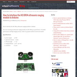
Its stable performance and high ranging accuracy make it a popular module in electronic market. Specifications: power supply : 5V DC quiescent current : <=2mA effectual angle : <= 15° ranging distance : 3 cm – 400 cm resolution : 0.3 cm There are 4 pins out of the module : VCC , Trig, Echo, GND . Pull the Trig pin to high level for more than 10us impulse, so the module starts ranging;If you find an object in front , Echo pin will be high level, and based on the different distance, it will take the different duration of high level. Arduino - HC-SR04 ultrasonic distance sensor. Last Christmas as part of my stocking fillers I got an HC-SR04 ultrasonic distance sensor.
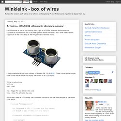
Like most of my electronic bits it's a cheap generic device from ebay. It's a small sensor that is suppose to do the same thing as the Ping sensor but for less money. I finally unwrapped it and found a library for Arduino IDE 1.0 at HERE. There is even some sample code to read the HC-SR04 and display the results on an LCD display. Wiring up DHT11 Temp & Humidity sensor to the Arduino.
DHT11 Temperature and Humidity sensor The DHT11 is chosen because it is lab calibrated, accurate and stable and its signal output is digital.

Most important of all, it is relatively inexpensive for the given performance. Below is the pinout of the sensor. How to use Nokia F-bus to send an SMS message. A few months ago I was looking into how to use Fbus with a Nokia phone but didn’t have much luck and instead just wired up the keypad.
I decided to revisit Fbus and this time happened to find some AVR code which could send/receive SMS’s so now I’m able to send an SMS using the Arduino and I’ll explain how we do this. Before I go any further the 3 resources I used were:Embedtronics – F-bus packet explanation with some examples of a packetAvr and nokia3310 interface(sms) project on AVRfreaks – Code for an AVR to send/receive SMSGnokii – F-bus documentation and code to run on a computer. Connect the components. How to use Pyroelectric ("Passive") Infrared Sensors (PIR) HMC5883L Compass Tutorial with Arduino Library - Tutorials - Love Electronics. Using a magnetometer can be a little tricky, especially if your unsure about the formulas to use to get the correct bearing and when other magnetic objects are interfering with your signal.
We've created a library for our HMC5883L Breakout Board , which will also be compatible with other HMC5883L breakout boards made by other manufacturers. Join us whilst we cover the following: Understand what is a magnetometer and how they work. Introduce the HMC5883L Arduino Library Explain how to extract data from the HMC5883L. Explain how to calculate a bearing from this data. How do compasses work? Firstly an introduction, a (standard handheld) compass works by aligning itself to the earths magnetic field. Arduino GSM GPRS and GPS shield. Shield for Arduino designed and based on the module GSM/GPRS SIM900 or the GSM/GPRS & GPS module SIM908, to make calls, voice and data connections via GPRS.
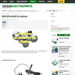
This new version (old Arduino GSM shield) has several new hardware features, that allow maximum customization and provide many configurations. We begin with the supply circuit a simple LM7805. To work, it is necessary to provide an input voltage between 7.5V and 12V. As shown in the circuit diagram, the input voltage, after being stabilized at 5 V, is reduced to 4.3 V by using a diode and provide power to modules that need a voltage between the 3.2 and 4.8 V.
During the operations such as the use of GPRS, the module absorbs a current of about 1 A, therefore it is necessary that the power source is able to provide this current intensity. An important technical feature is the serial adapter for the communication between the GSM module and Arduino. The news that is immediately evident is the presence of two jacks for audio. SIM900.h. Arduino Motion Sensor. Make your own Arduino motion sensor / detector.
Maybe you want something to happen when you walk into a room, like have the lights turn on, or have your theme song play whenever you enter. This tutorial will show you how to get your to Arduino sense motion around it. Software used in this tutorial can be downloaded here: Atelier Arduino - Arduino projects - Labo4G. Floss Manuals francophone - Lire. Ce projet permet de monter plusieurs LED sur une carte Arduino. Les LED sont ensuite pilotées à partir de certaines touches du clavier de votre ordinateur pour en faire un magnifique jeu de lumière.