
Free Circuit Diagram and Electronic Wiring - WiringCircuit. Free Circuit Diagram and Electronic Wiring - WiringCircuit. The schematic diagram shown right here is the automatic switching-on emergency light circuit which is controlled using IC.
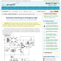
The most important capabilities of this circuit are: automatic switching-on of the light on main power failure and battery charger with overcharge protection. When mains electrical power is absent, relay RL2 is in deenergised state, feeding DC source from battery to inverter section via its N/C contacts and switch S1. The inverter section comprises IC2 (NE555) that is applied in stable mode to generate sharp pulses / wave with frequency of 50 Hz to drive the power MOSFETs.
The output of IC3 is fed to gate of MOSFET (T4) directly while it is applied to MOSFET (T3) gate just after inversion by transistor T2. Therefore the power amplifier designed close to MOSFETs T3 and T4 functions in push-pull mode. The output across secondary of transformer X2 can simply drive a 230-volt, 20-watt fluorescent tube. Full Bridge Inverter Circuit Diagram. How to Make a Simplest Inverter Circuit. This super simple design of an inverter circuit does not limit it in any way from providing a high output power and an efficiency of a good 75%.

Learn how to build an inverter that will satisfy most of your power requirement at quite an affordable cost.The article deals with the construction details of a mini inverter. Read to know how to build an inverter which can provide reasonably good power output and yet is very affordable and sleek. There may be a huge number of inverter circuits available over the internet and electronic magazines. But these circuits are often very complicated and hi-end type of inverters. Inverter circuit diagram. Cheap 12V to 220V Inverter. Posted Apr 17, 2013 at 8:43 am Even though today’s electrical appliances are increasingly often self-powered, especially the portable ones you carry around when camping or holidaying in summer, you do still sometimes need a source of 230 V AC – and while we’re about it, why not at a frequency close to that of the mains?

As long as the power required from such a source remains relatively low – here we’ve chosen 30 VA – it’s very easy to build an inverter with simple, cheap components that many electronics hobbyists may even already have. Though it is possible to build a more powerful circuit, the complexity caused by the very heavy currents to be handled on the low-voltage side leads to circuits that would be out of place in this summer issue. Let’s not forget, for example, that just to get a meager 1 amp at 230 VAC, the battery primary side would have to handle more than 20 ADC!. How a Pure Sine Wave Inverter Works Circuit Diagrams. Free Circuit Diagram and Electronic Wiring - WiringCircuit. How an Inverter works. - Electronic Circuits and Diagram-Electronics Projects and Design.
Inverter.
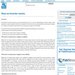
An inverter is used to produce an un-interrupted 220V AC or 110V AC (depending on the line voltage of the particular country) supply to the device connected as the load at the output socket.The inverter gives constant AC voltage at its output socket when the AC mains power supply is not available. Lets look how the inverter makes this possible.To grasp the functioning of an inverter,we should consider in the following situations. When the AC mains power supply is available.when the AC mains power supply is not available. When the AC mains power supply is available. When the AC mains power supply is not available.
SIMPLE INVERTER CIRCUIT 230V. Now i am with another SIMPLE project, INVERTER.
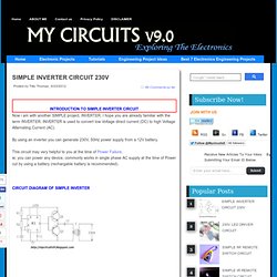
I hope you are already familiar with the term INVERTER. 1000w dc-ac inverter circuit diagram. 1000w dc-ac inverter circuit diagram. 250 to 5000 watts PWM DC/AC 220V Power Inverter. This is a heavy duty design of a Pulse Width Modulator DC/AC inverter using the chip SG3524 .
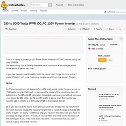
I've been using it as a backup to power up all my house when outages occur since aprox. 6 years non stop. If you like the work and intend to build the circuit don't forget to click on the "I made it" button so I know how many people benefit from the design, Thanks. Notes: 1> The schematic circuit design is for a 250 watt output, while the pics are of my 1500 watts inverter that i built, to increase the power of the circuit you have to add more of the Q7 and Q8 transistors in parallel, each pair you add will increase your power by 250 watts, ex: to get 750 watts of power from the inverter you need to add in parallel 2 of Q7 and 2 of Q8 to the original design. Note15-Feb-16: (48V center tapped means: P:48V "24-0-24" / S:220V) Note18-Feb-16: Test your transformer before doing this project. ****Do not supply the driver circuit with more than 24VDC max. because the voltage regulator "7812" will burn. 500W low cost 12V to 220V inverter - circuit diagrams, schematics, electronic projects.
Attention: This Circuit is using high voltage that is lethal.
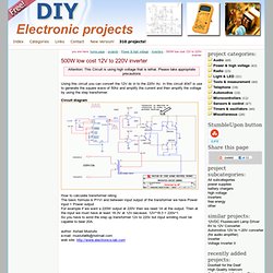
Please take appropriate precautions Using this circuit you can convert the 12V dc in to the 220V Ac. In this circuit 4047 is use to generate the square wave of 50hz and amplify the current and then amplify the voltage by using the step transformer. Circuit diagram How to calculate transformer rating The basic formula is P=VI and between input output of the transformer we have Power input = Power output For example if we want a 220W output at 220V then we need 1A at the output. Author: Ashad Mustufa e-mail: mustufa66@hotmail.com web site: 2000 watt inverter circuit diagram/ 24V 2KVA circuit diagram. 1000 watt power inverter circuit diagram ~ CircuitsTune. Solar Power Inverter Circuit. A compact and portable 12V solar power inverter circuit that will keep away darkness.
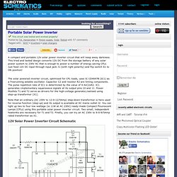
This tried and tested design converts 12V DC from the storage battery of any solar power system to 230V AC that is enough to power a number of energy saving CFLs. Just feed 12V DC input through input jack J1 (with right polarity) and flip switch S1 to ON position! The solar powered inverter circuit, optimised for CFL loads, uses IC CD4047B (IC1) as a freerunning astable oscillator.
Capacitor C2 and resistor R2 are timing components. The pulse repetition rate of IC1 is determined by the value of 4.4xC2xR2. Testing, Troubleshooting an Inverter Circuit - Discussion. Continued from HERE Hi Swagatam, one more question.

I don't have any 10K Dual Pot, but I do have a 50K Dual Pot, is that OK?? Hi Ali, Just connect 22k fixed resistors across each transistor base and ground and then you may connect the 50K Dual pot leads across these resistors, that should imitate a 10k pot variations quite closely. Regards. Hi Swagatam, so just to be clear, you want me to remove the 10K resistors connected to the Base of each Transistor and replace with 22K resistors and connect another two 22K resistors from the Emitters to Ground . Sincerely Ali. PWM inverter circuit based on SG3524 : 12V input, 220V output, 250W. PWM inverter circuit 250W PWM inverter circuit SG3524.
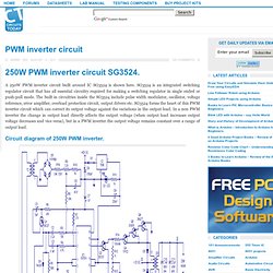
A 250W PWM inverter circuit built around IC SG3524 is shown here. SG3524 is an integrated switching regulator circuit that has all essential circuitry required for making a switching regulator in single ended or push-pull mode. The built in circuitries inside the SG3524 include pulse width modulator, oscillator, voltage reference, error amplifier, overload protection circuit, output drivers etc.
SG3524 forms the heart of this PWM inverter circuit which can correct its output voltage against the variations in the output load. DC-AC Inverter, Convert 12V DC Voltage to 110/220V AC Voltage - HQEW.net. Inverter. Power Inverters 12V to 230V contents: construction plans, technical description Version of Nov.8th,1999 Rev. 3.1 Fig. 1: 1000 VA-Inverter 12 Volt -> 230 Volt An inverter allowes the use of 230V electrical appliances from a car battery or a solar battery.
Fig. 2: Sine-wave voltage and conventional square wave voltage with both 230 Volt rms Fig. 2 shows a sine- as well as a square wave voltage with in each case an rms of 230 Volt. Our inverter works with a trick, to obtain the same results from square wave voltage as for sine-wave voltage. Fig. 3: Square wave voltage with duty cycle 25% for 230 Volt rms ("modified sine") Square wave voltage in fig. 3 developes the same peak value as sine-wave voltage of 230 Volts, i.e. 230 Volt * Ö 2 = 325 Volts and nevertheless thereby obtains the demanded rms of 230 V.