
$8 Lamp (Outlet) "Smart Plug" Module. Hi, Sorry I Think I expressed myself to short and incorrect on my way to work.
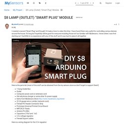
I really like this Project. My personal problem is that when you have many sensors, sooner or later you run out of old chargers Therefore for the relay (wallplug) it would be nice to find a small ac/dc power supply, which is easy to integrate into the breadboard/pcb. The Meanwell that I linked to i also availible in 5w, but personally I had some problems in the past, with the current consumption of the relays, using sub wall-warts. Mean well have nice quality but pricing is quite high. Light_Switch_XBee_Example_Project-Series_1. Light_Switch_XBee_Example_Project-Series_1. Yet Another Arduino 110v Power Controller. Tools Needed: Needle Nose Pliers Wire Cutters and strippers Screw driver Soldering Iron Multimeter Materials: Deep metal 4 gang output box and cover Wire clamps Two 15Amp outlets Four 5v 10Amp relays (such as Jameco’s 843155) A ULN2803A (such as Jameco’s 34315) A 5volt – 500ma Wall Wart (such as Jameco’s 164101) A length of 5-conductor wire (I used Cat5 cable) Household current rated wire with a male three-prong connector at one end.
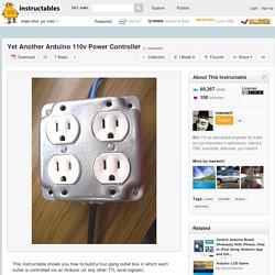
Miscellaneous wire and solder 5 minute epoxy Wire Nut Theory of Operation: The electricity flow to each outlet of a four-outlet household current box is controlled via TTL level signals (such as the output pins of an Arduino). Five wires are connected from the Arduino to the outlet box, four wires being connected to four Arduino output pins and the fifth to the Arduino’s ground pin. Using Relays with Arduino – Turning on the Lights. Warning!!!

This project deals with AC electricity which is dangerous if you don’t know how to treat it safely. You must treat electricity with caution. There are many books and websites about electrical safety procedures and if you’re not sure how to be safe you should read that information. The most basic advice I can give is always assume any exposed wires are live and touching them will hurt a lot at best and kill at worst. Microcontrollers are good at controlling small devices, but frequently we DIY-ers want to use them to control things that aren’t so micro. The first thing you need is a cheap extension core that you are willing to cut in half. I spliced the relay into the black wire on my power cord. The last step and the one that makes this project useful is getting the microcontroller to control this relay. In this circuit the transistor acts as a switch and it allows you to turn on the relay.
PowerSwitch Tail II and Arduino. Summary Example of controlling the PowerSwitch Tail II, using an Arduino.
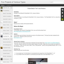
Description This is an example of controlling the PowerSwitch Tail II, using an Arduino. The PowerSwitch Tail II is a relay that is enclosed in a case. Why? Because we can easily control physical devices. Before We Begin PowerSwitch Tail II This example uses using the PowerSwitch Tail II, you can find the product here: Arduino This example uses the Arduino Duemilanove version of the Arduino board. Upload Code to Arduino If you don't have the Arduino environment, download it from the Arduino site ( From here, copy the code from the bottom section labeled "The Code".
Hooking it up Simply enough here's how this works. Fun Projects of Various Types: PowerSwitch Tail II and Arduino. Arduino WiFi Power Switch & Energy Monitoring Device - Open Home Automation. In this project, we are going to build an open-source version of WiFi power switches that you can buy in many stores.
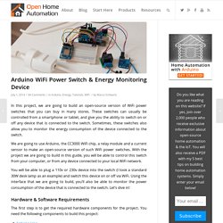
These switches can usually be controlled from a smartphone or tablet, and give you the ability to switch on or off any device that is connected to the switch. Sometimes, these switches also allow you to monitor the energy consumption of the device connected to the switch. We are going to use Arduino, the CC3000 WiFi chip, a relay module and a current sensor to make an open-source version of such WiFi power switches. ESP8266 Projects: P3 - WIFI Mains Power Dimmer / Switch with CBDBv2.
Taking Basic Electronics to the Internet (IoT) This is tutorial four of the series where I take electronic devices which you normal control using an Arduino, to the internet using a Spark Core.
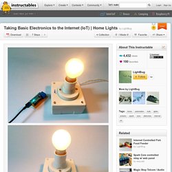
After talking about the basics it time to raise the level a little bit and start taking everyday electronics to the internet. In this tutorial I'm going to show you how to control your everyday home lighting system over the internet using a web browser. This system will also serve as a basic block of designing an advance home automation system. I have tried to keep this instructable as simple as possible, so that no one gets left behind. You can check out my previous Instrutables, before diving right into this one as those Instructables are quite simple and help in getting started with the Particle Core or Particle Photon. So lets get started. Learn.adafruit. PowerSwitch Tail II - COM-10747. SparkFun Solid State Relay Kit - KIT-10684.
Description: A solid state relay (SSR) is just what it sounds like; an IC that acts like a mechanical relay.

They allow you to control high-voltage AC loads from lower voltage DC control circuitry. Solid state relays, however, have several advantages over mechanical relays. One such advantage is that they can be switched by a much lower voltage and at a much lower current than most mechanical relays. Also, because there’s no moving contacts, solid state relays can be switched much faster and for much longer periods without wearing out. SparkFun Beefcake Relay Control Kit - KIT-11042. Wifi Switch board or Smart Plug with Esp8266, Attiny 85 & PIR Sensor with android app. First of all arrange your esp and FTDI (USB-UART) and connect them as shown figure (note: external 3V3 is better for your esp8266 instead of using the 3V3 from FTDI chip )The esp8266 firmware flasher and binary can be downloaded here or from this instruct able.
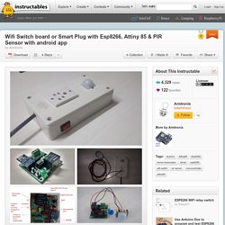
You can use this firmware v0.9.5 AT Firmware.bin .Use a low numbered COM port 6 or less, you can change this in the device manager if needed .You will find in windows handling comports above COM10 is slightly different so a lot of software will trouble you. Power on the esp8266 and run the flash tool, load the binary file .You change the COM port to match your USB-UART number, leave the second number (offset) at 0x0000 )Hit download, should see this, I've always gotten this last warning "Leaving...Failed to leave Flash mode" connecting .... Erasing flash...