
Oscillator Waveform Conversion. Waveform Conversion, Part I - Sine to Square The system designer is often called upon to convert a sine wave from an oscillator, power splitter, or other RF device into a square wave suitable for driving a logic device.
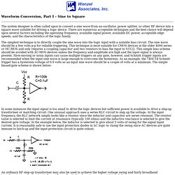
There are numerous acceptable techniques and the best choice will depend upon several factors including the operating frequency, available signal power, available DC power, acceptable edge speeds, and the characteristics of the logic family. The simplest technique is to directly couple the sine wave into the logic input with a suitable bias circuit. The sine wave should be a few volts p-p for reliable triggering. This technique is most suitable for CMOS devices in the older 4000 series or HC-MOS and only requires a coupling capacitor and two resistors to bias the input to VCC/2.
In some instances the input signal is too small to drive the logic devices but sufficient power is available to drive a step-up transformer or matching circuit. [navigate.html] DDS-60 Kit from the AmQRP. Top View (click for larger image) Bottom View (click for larger image) . | Overview | Schematic | Ordering | Availability | Ways to Use | | Assembly & User Manual | Quick Assy Guide | Builder's Notes | Article: "Working with Surface Mount Technology (SMT) Parts" Tech Topic: DDS-60 Spectral Purity Study Tech Topic: DDS-60 Temperature Analysis Sold Out!
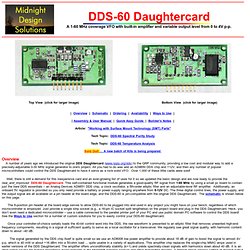
Overview A number of years ago we introduced the original DDS Daughtercard (www.njqrp.org/dds) to the QRP community, providing a low cost and modular way to add a precisely-adjustable 0-30 MHz signal generator to one's project. Well, there is still a demand for this inexpensive card and an ever-growing list of uses for it so we updated the basic design and are now ready to provide the new_and_improved DDS-60 Daughtercard. The 8-position pin header at the board edge serves to allow DDS-60 to be plugged into and used in any project you might have on your bench, regardless of which microcontroller is employed.
Schematic To Order Go back. Cds.linear.com/docs/Application Note/an18f.pdf. Analog Electronics: Basic Circuits of Operational Amplifiers. Analog computer 1. Back to homepageAnalog computer 1 Analog computer is a type of computer that works with continuously changing variables, as opposed to digital computer that uses discrete values.
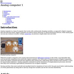
Digital computers are almost always electronic or electromechanical devices, while analog types can use any continous variable: voltage, water flow, air pressure, length (slide rule) and other. Finished analog computer. While first modern computers were analog electromechanical differential analyzers in the 1930s, soon thereafter they were faced with competition from electronic digital computers.
By 1960s, pace of miniaturization of digital components meant that digital computers became less expensive than analog ones, while being able to produce exact answers, a must for many human endeavors. Analog computers continued in use for simulation of complex physical processes, but even here they were eventually superseded by simulations run on digital computers. I made a schematic based on the original article.
Analog Innovations. Electret Microphone Preamplifier - Мозилин фајерфокс (Mozilla Firefox)