
Www.guitarpcb.com/PDF Files/DLay v2 BuildDoc.pdf. The Valve Wizard. Small Time: A Delay / Echo with Tails The Small Time delay is a straightforward delay/echo effect, with tails.
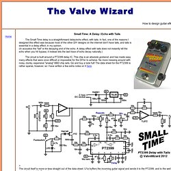
In fact, one of the reasons I designed this effect was because most of the other DIY designs on the internet don't have tails, and tails is essential in a delay effect, in my opinion. (In acoustics the "tail" is the decaying end of the echo. A delay effect with tails does not instantly kill the echo when you hit bypass; it instead lets the last trace of echo decay naturally.) The circuit is built around a PT2399 delay IC. > The circuit itself is more-or-less straight out of the data sheet.
The JFET acts as an analog switch. Pin-6 of the PT2399 is a voltage source that rests at half the chip's supply voltage, which is provided by a 5V regulator in this case, so pin-6 will be at 2.5V. Technical details: Input impedance = 1M ohms Output impedance = 100 ohms Current consumption = 22mA when active. Holtek echo.gif (1435×1080) Topic: D'Lay v2 - GuitarPCB.com. The Rules are Simple. Read before posting. People friendly environment - It is OK to ask questions.No bad language, flaming or abusing your posting privilege! No spamming, porn, advertising or any other inappropriate forum behavior.No discussion regarding currently commercially available pedals in regards to disection, schematics or producing any form of circuit layout.
TM names are to be respected.No use of avatars, pictures or words that could be considered offensive to others in our forum. I have children that read my site, so do others. Membership implies agreement to the rules set forth here: LEGAL INFO & FAQ GuitarPCB.com reserves the right to choose its Members and Customers. Disclaimer: GuitarPCB makes no promises or guarantees that you will successfully complete your pedal in a satisfactory manner.
If you do not agree to the above Statements remove yourself as a Member or ask for removal. Amendment of the Terms Suspension and Termination of Access and Membership. The Valve Wizard. Spring Reverb Drivers Information on driving spring reverb using valves (tubes) seems to be rather sparse, so the following is presented as a guide to valve amp designers.
This article considers only the driver stage, and not the reverb recovery stage (which is usually a simple triode gain stage, unfortunately). More information on reverb tanks is also available at Rod Elliot's site. How Spring Reverb works, in brief: The input transducer of a reverb tank is a coil of wire wound around an iron core. How much current is required? The voltage required to achieve the Nominal Drive Current can be found from Ohm's law: V = IZ Where Z is the impedance of the coil, which is normally quoted at 1kHz. For example, if a type A tank is rated as 8 ohms at 1kHz and has 124 turns; I(nominal) = Amps per turn / number of turns.
So the required drive voltage is; V = 0.028 * 8 = 0.2V This implies that the power dissipated in the coil is 6mW. Cheap current source drivers: