
EL SERVOMOTOR. Un Servo es un dispositivo pequeño que tiene un eje de rendimiento controlado.
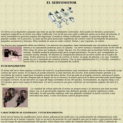
Este puede ser llevado a posiciones angulares específicas al enviar una señal codificada. Con tal de que una señal codificada exista en la línea de entrada, el servo mantendrá la posición angular del engranaje. Cuando la señala codificada cambia, la posición angular de los piñones cambia. En la práctica, se usan servos para posicionar superficies de control como el movimiento de palancas, pequeños ascensores y timones. Ellos también se usan en radio control, títeres, y por supuesto, en robots. Los Servos son sumamente útiles en robótica. Un servo normal o Standard como el HS-300 de Hitec tiene 42 onzas por pulgada o mejor 3kg por cm. Modbus. Modbus is a serial communications protocol originally published by Modicon (now Schneider Electric) in 1979 for use with its programmable logic controllers (PLCs).
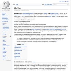
Simple and robust, it has since become a de facto standard communication protocol, and it is now a commonly available means of connecting industrial electronic devices.[1] The main reasons for the use of Modbus in the industrial environment are: developed with industrial applications in mindopenly published and royalty-freeeasy to deploy and maintainmoves raw bits or words without placing many restrictions on vendors Modbus enables communication among many (approximately 240) devices connected to the same network, for example a system that measures temperature and humidity and communicates the results to a computer.
Table of Contents - Practical Process Control by Control Guru. CTM: PID Tutorial. In this tutorial we will introduce a simple yet versatile feedback compensator structure, the Proportional-Integral-Derivative (PID) controller.
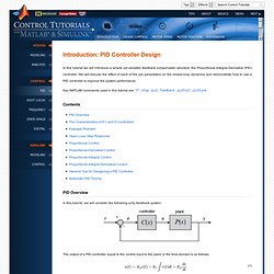
We will discuss the effect of each of the pid parameters on the closed-loop dynamics and demonstrate how to use a PID controller to improve the system performance. Key MATLAB commands used in this tutorial are: tf , step , pid , feedback , pidtool , pidtune Contents PID Overview In this tutorial, we will consider the following unity feedback system: The output of a PID controller, equal to the control input to the plant, in the time-domain is as follows: First, let's take a look at how the PID controller works in a closed-loop system using the schematic shown above. ) represents the tracking error, the difference between the desired input value ( Proporcional integral derivativo. Un PID es un mecanismo de control por realimentación que calcula la desviación o error entre un valor medido y el valor que se quiere obtener, para aplicar una acción correctora que ajuste el proceso.
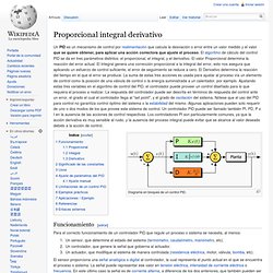
El algoritmo de cálculo del control PID se da en tres parámetros distintos: el proporcional, el integral, y el derivativo. El valor Proporcional determina la reacción del error actual. El Integral genera una corrección proporcional a la integral del error, esto nos asegura que aplicando un esfuerzo de control suficiente, el error de seguimiento se reduce a cero. PID controller. Some applications may require using only one or two actions to provide the appropriate system control.
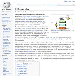
This is achieved by setting the other parameters to zero. A PID controller will be called a PI, PD, P or I controller in the absence of the respective control actions. PI controllers are fairly common, since derivative action is sensitive to measurement noise, whereas the absence of an integral term may prevent the system from reaching its target value due to the control action.
History and applications[edit] PID theory developed by observing the action of helmsmen. The Navy ultimately did not adopt the system, due to resistance by personnel. Electronic analog controllers can be made from a solid-state or tube amplifier, a capacitor and a resistor. Hysteresis. Such loops may occur purely because of a dynamic lag between input and output.
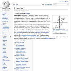
This effect disappears as the input changes more slowly. This effect meets the description of hysteresis given above, but is often referred to as rate-dependent hysteresis to distinguish it from hysteresis with a more durable memory effect. Etymology and history[edit] The term "hysteresis" is derived from ὑστέρησις, an ancient Greek word meaning "deficiency" or "lagging behind". It was coined around 1890 by Sir James Alfred Ewing to describe the behaviour of magnetic materials. Some early work on describing hysteresis in mechanical systems was performed by James Clerk Maxwell. Types of hysteresis[edit] Ladder logic. This article is about the programming language.
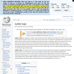
For the FIRST competition, see Ladder Logic. Ladder logic was originally a written method to document the design and construction of relay racks as used in manufacturing and process control. Each device in the relay rack would be represented by a symbol on the ladder diagram with connections between those devices shown. In addition, other items external to the relay rack such as pumps, heaters, and so forth would also be shown on the ladder diagram. See relay logic. Deadband. Input and output of the deadband operator.
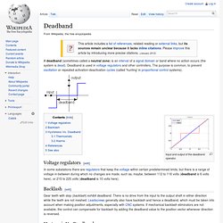
Voltage regulators[edit] In some substations there are regulators that keep the voltage within certain predetermined limits, but there is a range of voltage in-between during which no changes are made, such as, maybe, between 112 to 118 volts (deadband is 6 volts here), or 215 to 225 volts (deadband is 10 volts here). Backlash[edit] Gear teeth with slop (backlash) exhibit deadband.
There is no drive from the input to the output shaft in either direction while the teeth are not meshed. Hysteresis Vs. Deadband is different from hysteresis.