
The cheapest dual trace scope in the galaxy. This submini USB scope is based on a Atmel Tiny45 cpu and cost less than 5€ with a homemade pcb It has 2 analog inputs and can supply 5V ont the 4 pins header on the right.
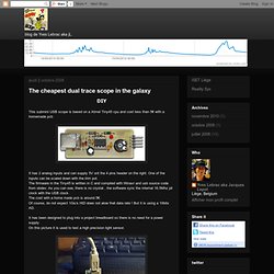
One of the inputs can be scaled down with the trim pot. The firmware in the Tiny45 is written in C and compiled with Winavr and usb source code from obdev. As you can see, there is no crystal , the software sync the internal 16.5Mhz pll clock with the USB clock. The cost with a home made pcb is around 5€.Of course, do not expect 1Gs/s HID does not alow that data rate ! It has been designed to plug into a project breadboard so there is no need for a power supply.On this picture it is used to test a high precision light sensor. It does connect to a PC with usb in HID mode, without the need to install any specific driver. Here is the schematic, so simple ! Thank you to[Milka2009] who made a nice video Bill of material eagle files: usbscope-tiny.zip. Arduino EMF detector. Looking at the world through a CD. How to Design a Square or Triangle Wave Oscillator from a 555-Timer Integrated Circuit.
Current and Voltage meter. FIRSTLY A WARNING.
Any system with 200V at 30A is unquestionably LETHAL. I once got to observe what 220VAC @ (probably) 50-100A could do; I was getting gas one morning at a local Circle K, and next door a "technician" was working on an HVAC unit on top of a burger joint. Well, he didn't follow proper lockout/tagout procedures (or hell, just remove the main fuses or drop the breaker, or - any number of things that you would think someone with "experience" would know to do), and somehow created a short. Very loud buzzing whoosh noise that lasted a couple of seconds with all I can describe as an "electrical jet flame" (corona discharge?) Shooting out about 3 feet. She's a beast, but one that will treat you ok as long as you respect and understand her. /don't ask me where that came from...
Arduino test: voltmeter. First experiment with Arduino.
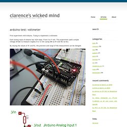
Trying to implement a voltmeter. Each analog input of Arduino has 1024 steps. From 0 to 5 volt. This experiment used a simple voltage divider to measure roughly 0 to 12 volt (using 50k as R1 and 4k3 as R2). Arduino power meter - Electrical Engineering - Stack Exchange. ICL7107 / ICL7106 - Digital Voltmeter. Led display digital Voltmeter - circuit diagrams, schematics, electronic projects. Front side Copyright of this circuit belongs to smart kit electronics.
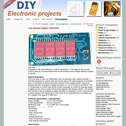
In this page we will use this circuit to discuss for improvements and we will introduce some changes based on original schematic. General Description This is an easy to build, but nevertheless very accurate and useful digital voltmeter. It has been designed as a panel meter and can be used in DC power supplies or anywhere else it is necessary to have an accurate indication of the voltage present.
The circuit employs the ADC (Analogue to Digital Converter) I.C. CL7107 made by INTERSIL. Technical Specifications - Characteristics Supply Voltage: ............. +/- 5 V (Symmetrical) Power requirements: ..... 200 mA (maximum) Measuring range: .......... +/- 0-1,999 VDC in four ranges Accuracy: ....................... 0.1 % FEATURES - Small size - Easy construction - Low cost. - Simple adjustment. - Easy to read from a distance. - Few external components.
Schematic (fixed 22-2-04) 7-segment display pinout MAN6960 back side. DC Voltmeter. How to sense 12v or Higher with Arduino?