
Cook Your Own Distortion. Making your own distortion design is easy.

So why not design your very own distortion effect? [ Back to Main | Download ] History of Distortions In the mid 50's, when electric guitars became popular, all amplifiers were designed for vocals, and they didn't really give the edge guitarists wanted. The only way to get distortion was to turn volume to eleven and hope the tubes didn't melt (or the neighbors didn't call the cops =).
Types of Distortion When talking about distortion, you can usually hear the words overdrive, distortion, fuzz and crunch. Creating distortion The ultimate distortion/overdrive comes from tubes which are overdriven so that it creates a smooth singing sound. 1) Overdriving transistors Just like overdriving tubes, transistors are being overdriven by setting them to run at the top of the amplification range. 2) "Hard" diode clipping This is a very common way to create distortion. 3) "Soft" diode clipping Another very common method. 4) Special methods Opamps.
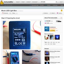
Electricity & magnetism test questions flashcards. Current amplifier. Preparing the circuit. Since I have no experience in electronics whatsoever, this was the toughest part for me to find out.

Other instructables had no good explaining on this subject. So for everyone who's new to this electronics stuff and have no idea what they're doing, here is some explaining for the circuit. 1. How many LED's to use? The average LED needs 3v to work. So if you use a 12v adapter with the 3v LED's its: 12 / 3 = 4 LED's You can also put LED's parallel in the circuit. 2. U.S.Navy NEETS program. College Instrumentation Specialist - NEETS. * These files are Adobe Acrobat files that are 100-400 pages in length and depending on your ISP connection speed may take some time to open.

You can also save these files directly to your computer without opening them by right-clicking on the link then select "Save Target As". All text below is copied directly from the forward that is in each NEETS manual: The Navy Electricity and Electronics Training Series (NEETS) was developed for use by personnel in many electrical and electronic related Navy ratings. Written by, and with the advice of, senior technicians in these ratings, this series provides beginners with fundamental electrical and electronic concepts through self-study. The presentation of this series is not oriented to any specific rating structure, but is divided into modules containing related information organized into traditional paths of instruction. Module 8 - Introduction to Amplifiers, covers amplifiers.
Circuit Theory/Laplace Transform. Laplace Transform[edit] The Laplace Transform is a powerful tool that is very useful in Electrical Engineering.

The transform allows equations in the "time domain" to be transformed into an equivalent equation in the Complex S Domain. The laplace transform is an integral transform, although the reader does not need to have a knowledge of integral calculus because all results will be provided. This page will discuss the Laplace transform as being simply a tool for solving and manipulating ordinary differential equations. Laplace transformations of circuit elements are similar to phasor representations, but they are not the same. Download Center. Download Center - EEP (Learning center for electrical engineers) Welcome to EEP’s Download Center! There are three main sections which covers electrical books & guides, software & tools and design documentation.
Feel free to explore our great recourses, and if you have any suggestions or complaints please contact us. EEP’s Download Center provides greatest resource for education and learning in field of electricity science. All documents are completely free to download. Books & Guides Electric power books are divided into few sections, so it is easy for power engineers to find appropriate book, guide or information related to power engineering, automation, industry etc. . - Electrical Eng. Explore section Software & Tools Electrical design without appropriate software and tools is impossible to imagine.
. - CalcuLuX Area - DIALux - Relux - Ecodial - Visual Design Docs Almost every electrical design project has some documents repeating from one to another project with some modifications. FEEE - Fundamentals of Electrical Engineering and Electronics: Table of Contents. Electrical Engineering Calculators. Series and parallel circuits. A series circuit with a voltage source (such as a battery) and 3 resistors A circuit composed solely of components connected in series is known as a series circuit; likewise, one connected completely in parallel is known as a parallel circuit. In a series circuit, the current through each of the components is the same, and the voltage across the circuit is the sum of the voltages across each component.[1] In a parallel circuit, the voltage across each of the components is the same, and the total current is the sum of the currents through each component.[3] In a series circuit, every device must function for the circuit to be complete.
One bulb burning out in a series circuit breaks the circuit. In parallel circuits, each light has its own circuit, so all but one light could be burned out, and the last one will still function. Free Electrical Engineering Help - Answers to Electrical Engineering Homework Questions. Free Electrical Engineering Help - Answers to Electrical Engineering Homework Questions.