
Solar powered, Wireless autonomous radiation sensor network node. I designed a system a few months ago that had the aim to track the amount of radiation of my backyard over a period of time.
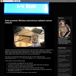
I figured that the least cumbersome way to keep track of the count-rate was to make the radiation sensor post the data directly to the internet, via cosm Xively. Cosm Xively is basically an 'internet-of-things' platform where devices can freely post, access and share data points. This project can be particularly interesting for those who, like me, want to keep track of the relative radiation rates for some reason.
(This is not a radiation dosimeter, hence the 'relative count rate') I found it worthy to share this design because: It is solar powered, and (energetically) fully self sufficient.It connects to the internet via Wi-fi, so no messy ethernet cables trailing across the backyard. Hardware overview Component list: First some pictures for a general overview of how one node is assembled. Arduino Passion: projects, news, tutorials, all Arduino resources you ever need. Solar Panel Charging Rechargeable Batteries. I made a weather station to continuously monitor daylight and temperature.
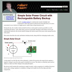
Since the project is placed away from the house, it is more convenient to use a battery to supply power, rather than a long extension cord. During the day, the weather station should run from a solar panel as much as possible to avoid consuming the battery. And, rather than a person occasionally checking on the battery levels and replacing the batteries, the circuit should recharge the battery pack from excess solar energy from the solar panel. This article describes the solar and battery backup circuit, along with the recharging results so far. Simple Solar Circuit Schematic of a simple solar-panel based circuit. » Battery level on JeeNode USB JeeLabs. The new JeeNode USB v3 includes a resistor divider to track the voltage level before the voltage regulator.
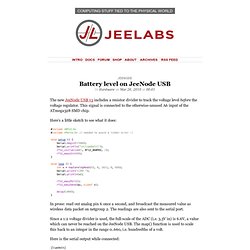
This signal is connected to the otherwise-unused A6 input of the ATmega328 SMD chip. Here’s a little sketch to see what it does: In prose: read out analog pin 6 once a second, and broadcast the measured value as wireless data packet on netgroup 2. » Measuring VCC via the bandgap JeeLabs. The ATmega’s (and ATtiny’s for that matter) all have a 10-bit ADC which can be used measure analog voltages.

These ADC’s are ratiometric, meaning they measure relative to the analog reference voltage (usually VCC). On a 5V Arduino, that means you can measure 0..5V as 0..1023, or roughly 5 mV per step. On a 3.3V JeeNode, the measurements are from 0 to 3.3V, or roughly 3.3 mV per step. There’s no point connecting VCC to an analog input and trying to measure it that way, because no matter what you do, the ADC readout will be 1023.
So can we figure out what voltage we’re running at? Well, there is also a “bandgap reference” in each ATmega/ATtiny, which is essentially a 1.1V voltage reference. Suppose we read out an ADC value “x” which represents 1.1Vwith 5V as VCC, that value would be around 1100 / 5000 * 1023 = 225whereas with 3.3V as VCC, we’d expect a reading of 1100 / 3300 * 1023 = 341more generally, 1100 / VCC * 1023 = xsolving for VCC, we get VCC = 1100 / x * 1023. Solar powered Arduino and attiny projects. Intro I've started creating a solar powered base platform for attiny or Arduino based projects.
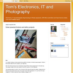
What is the real life need for such a project, you might ask. Well, the Atmel processors are amazingly energy efficient when programmed in the right way. Your project might run for over a year on a set of 2 normal 1.5V AA batteries. The example project to which I link in the end of this blog will signal the battery voltage level by blinking a led several times every 10 seconds. How long will this project run from batteries? In sleep mode my attiny84 uses 0.004mA. How to run an Arduino (clone) on a 9V battery for weeks or even months. About a year ago, I started building wireless sensors that needed to run on a battery.
I quickly found out however that this wasn’t going to be easy: A battery would only last for a few days, before it would be gone. Browsing around the internet, I learned about the fantastic work of Jean Claude Wippler of Jeelabs fame. JC has been working on wireless sensors for years and tackled the battery issue way before I did. So let me explain in my own way why you kill a battery in days and what you can/should do to fix this. Why will a standard Arduino eat a battery in days? Arduino separates itself from a bare ATMEGA from the hardware side of things are it’s form factor (allowing for the use of standard shields), standard USB interface, power regulation and some LEDs. How to go from this? So how do we go from this? On the software side On the software side we also have to do something: The Barebones Arduino is now taking 6mA instead of >15 mA, but still way too much.
Example Calculation Debugging.