
H-Bridge Motor Driver 1A. H-bridge - Electronics. Int motor1 = 2; //declares the first pin for the motor int motor2 = 4; //declares the other pin for the motor int motorpmw = 9; // this is the pmw that will set how much battery power the motor is getting (speed) void setup() pinMode(motor1, OUTPUT); // pinMode(motor2, OUTPUT); // these simply are declaring them as outputs pinMode(motorpmw, OUTPUT); // void loop() analogWrite(motorpmw, 255); // this is the analog speed value for the arduino (0-255) digitalWrite(motor1, HIGH); digitalWrite(motor2, LOW); //turns the motors on - forwards delay(1000); // resets the coding sequence and refiles all the commands under the y-drive of the mainframe. digitalWrite(motor1, LOW); digitalWrite(motor2, HIGH); //makes motor go backwards delay(1000); //summons demons to influence the creation of man into waiting for exactly 1 second.
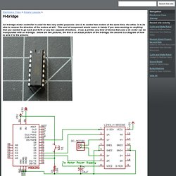
Quarkstream. An H-Bridge is like an electric double-switch, or double-relay.
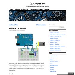
A small current from the Arduino at one of two pins can turn on a much larger current at two other pins. This is useful for controlling two-state devices, like motors that you want to run both forwards and backwards. For this project I used an SN75441 H-bridge chip. Example: Have the Arduino read the state of a switch to control a high-voltage motor running forwards and backwards. Schematic: D2, D3 and D4 are digital pins on the Arduino Program: int motorPin0 = 2; int motorPin1 = 3; int switchPin = 4; int state = 0; void setup() { pinMode(motorPin0, OUPUT); pinMode(motorPin1, OUTPUT); pinMode(switchPin, INPUT); void loop() { Arduino – Control a DC motor with TIP120, potentiometer and multiple power supplies. A quick circuit showing how to control the speed of a DC motor with a potentiometer with your Arduino board.
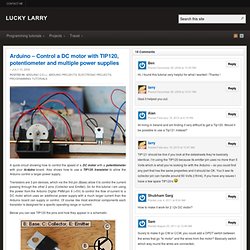
Also shows how to use a TIP120 transistor to allow the Arduino control a larger power supply. Transistors are 3 pin devices, which via the 3rd pin (Base) allow it to control the current passing through the other 2 pins (Collector and Emitter). So for this tutorial I am using the power from the Arduino Digital PWM pin 9 (+5V) to control the flow of current to a DC motor which uses an additional power supply with a much larger current than the Arduino board can supply or control. Of course like most electrical components each transistor is designed for a specfic operating range or current. Below you can see TIP120 the pins and how they appear in a schematic: So thats the transistor. The other item is the potentiometer, which is basically a variable resistor.
Arduino TIP120 Circuit Components. Ntrol a DC motor with Arduino and L293D chip. [ad#Google links] This is a quick guide with a bit of extra info (pin configurations etc..) that I’ve learnt along the way on how to use the L293D with the Arduino, showing that we can: A) Use a supplemental power source to power the DC motor B) Use the L293D chip to drive the motor C) Use a switch to change the direction of the motor UPDATE: If you intend to use this for robotics then please check out this page here to get the most out of this chip – I actually found the SN754410 easier to work with that the L293D, its exactly the same apart from it can handle more current Arduino obstacle avoidance robot L239D DC Motor Driver & Pin Configuration Although I’ve only used 1 motor, it is possible to use 2 motors on a single L293D chip, of course you then have to compensate on the current accordingly to ensure enough juice for both motors under peak load.
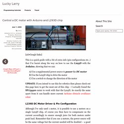
“The L293D is a monolithic integrated, high voltage, high current, 4-channel driver.” +tut moteur pas à pas 4 poles. Aillant récemment obtenu un module Arduino Uno, je me suis essayé à quelques bidouillages...
Voici donc comment j'ai procédé pour câbler et commander un moteur pas à pas 4 pôles, issu tout droit d'un vieux lecteur de CD-ROM : La document technique de ce genre de moteur est disponible ici : Pour réaliser ce montage il faudra aussi ce procurer un circuit intégré 754410 (QUADRUPLE HALF-H DRIVER) afin de donner un peu de puissance au moteur pas à pas. La documentation du CI est ici : On peut le trouver chez n'importe quel magasin d'électronique pour quelques euros. Pour connecter le CI au module Arduino, nous devons utiliser 4 E/S au choix (nommée ci-après A, B, C et D), l'alimentation 5V, la masse (GND) et l'alimentation en puissance issue du module Arduino (Vin). Voici le cablage : - Commande A, B, C et D sont a relier au 4 E/S choisies sur le module Arduino - Moteur A1, A3, B1 et B3 sont les quatre pôles du moteur (Voir ci-après) Le dessin n'est pas très lisible, vous pouvez zoomer un peu.
Il contrôle vos mains et vous apprend à jouer d'un instrument.