
555 Timer-Oscillator Tutorial. I nside the 555 timer, at fig. 3, are the equivalent of over 20 transistors, 15 resistors, and 2 diodes, depending of the manufacturer.
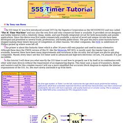
The equivalent circuit, in block diagram, providing the functions of control, triggering, level sensing or comparison, discharge, and power output. Some of the more attractive features of the 555 timer are: Supply voltage between 4.5 and 18 volt, supply current 3 to 6 mA, and a Rise/Fall time of 100 nSec. It can also withstand quite a bit of abuse. The Threshold current determine the maximum value of Ra + Rb. For 15 volt operation the maximum total resistance for R (Ra +Rb) is 20 Mega-ohm. The supply current, when the output is 'high', is typically 1 milli-amp (mA) or less. All IC timers rely upon an external capacitor to determine the off-on time intervals of the output pulses. Assume further that the applied voltage is 6 volts. Fig. 4-1, Change in the input pulse frequency allows completion of the timing cycle. Definition of Pin Functions: A Simple PWM Circuit Based on the 555 Timer.
One of the most fundamental problems in robotics is DC motor speed control.
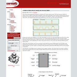
The most common method of speed control is PWM or pulse width modulation. Pulse width modulation is the process of switching the power to a device on and off at a given frequency, with varying on and off times. These on and off times are referred to as "duty cycle". The diagram below shows the waveforms of 10%, 50%, and 90% duty cycle signals. As you can see from the diagram, a 10% duty cycle signal is on for 10% of the wavelength and off for 90%, while a 90% duty cycle signal is on for 90% and off for 10%.
While many robot builders use a microcontroller to generate the required PWM signals, the 555 PWM circuit explained here will give the novice robot builder an easy to construct circuit, and good understanding of pulse width modulation. The 555 timer in the PWM circuit is configured as an astable oscillator. The pinouts for the 8 pin DIP package are as follows: LM555 Timer Circuits. The 555 Timer - Electronics in Meccano. The 555 Integrated Circuit (IC) is an easy to use timer that has many applications in Meccano modelling.
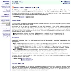
It is widely used in electronic circuits and this popularity means it is also very cheap to purchase, typically costing around 30p. Versions of the 555 are available for low current applications or use in extreme temperatures. A 'dual' version called the 556 is also available which includes two independent 555 ICs in one package. Output States The 555 relies on both analogue and digital electronic techniques to perform its functions, but if we consider its output only, it can be thought of as a digital device.
The output of the 555 can be in one of two states at any time, which means it is a digital output. Low is also known as 'space', or 'logic 0'. 555 Circuits In Electronics in Meccano, three of the most common 555 circuits will be introduced. The Astable Circuit produces a continuous train of pulses at any frequency you require.