
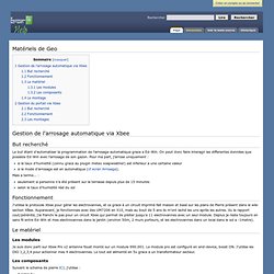
The Negawatt » XBee. Tweet-A-Watts: Wireless logging of point of consumption electricity data he Tweet-A-Watt DIY wireless power monitoring project is the brainchild of the generous Limor Fried (Lady Ada), of Adafruit Industries and ladyada.net.
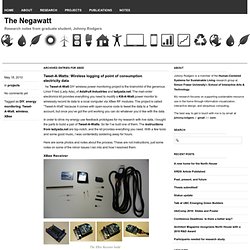
The mail-order electronics kit provides everything you need to modify a Kill-A-Watt power monitor to wirelessly record its data to a local computer via XBee RF modules. The project is called “Tweet-A-Watt” because it comes with open-source code to tweet the data to a Twitter account, but once you’ve got the unit working you can do whatever you’d like with the data. In order to drive my energy use feedback prototypes for my research with live data, I bought the parts to build a pair of Tweet-A-Watts.
So far I’ve built one of them. Here are some photos and notes about the process. Rob Faludi. Project Lab. Difficulty Level = 5 [What's this?]
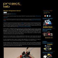
UPDATE: I have re-done this project using simple 434MHz RF transmitter/receiver devices. Check out the new project!. UPDATE: Also see this project for an easy way to display a temperature reading: Digit Shield Temperature Display. I decided to explore the more advanced features of XBee radios by building a remote temperature sensor. You can get quite a bit of control over an XBee radio without a microcontroller at all. For this project, I configured the radio at the sensor end to read the analog input of pin 19 every 4 seconds and to send a sensor reading packet. Input pin 19 on my sensor radio is configured (parameter D1) with value ’2′ which means that it will read analog input, and the IO sampling rate (parameter IR) is set to ’1000′ which sends a sample every 4096ms.
An LM34 temperature sensor outputs a variable voltage depending on the temperature. Why did I choose pin 19? Remote temperature sensor Here is the circuit for the remote sensor: Doublecommande2.4_sansfil. Sans fil Voir le fichier PDF de cette page sur http:/fr.groups.yahoo.com/group/Le_SUPERTEF ---> Fichiers Notre ami Jean Claude SIROT a franchi un pas de plus et nous propose le système de double commande sans fil qu'il a réalisé et expérimenté avec succès !
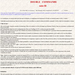
Nous lui laissons exposer sa solution dans les lignes qui suivent! Et si maintenant, on essayait d'aller plus loin dans la démarche, en supprimant tout bonnement le fil entre les émetteurs maître et élève ? Chiche ! Voilà déjà un petit moment que l'idée me trotte en tête et elle s'est affinée en créant la solution de double commande 2.4GHz, objet de la description ci dessus. XBee Accelerometer Demo - Wireless Tilt Mouse Application. XBee API pour pilotage à distance. Version mise à jour en avril 2011 Nous avons déjà utilisé précédemment les XBee très simplement pour faire une liaison série sans fil entre plusieurs modules (voir cet article), mais maintenant on va s’attaquer au mode "API" pour piloter à distance les ports entrée/sortie numérique ou analogique de plusieurs modules XBee sans utiliser de microcontrôleur supplémentaire.
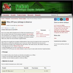
Cet article est le résultat de nos ateliers hebdomadaires. Nous avons tout appris de zéro concernant les XBee grâce aux différentes explications qu’on trouve sur Internet. Remercions tous ceux qui ont documenté leurs projets et qui contribuent par des fichiers, des codes sources, des articles. Parmi eux : Tom Igoe pour son livre "Making Things Talk" Daniel Menesplier pour sa doc en français sur son site web. [PoBot] XBee API pour pilotage à distance. Matériels de Geo - WIKI.Ed-Win. De WIKI.Ed-Win.
But recherché Le but étant d'automatiser la programmation de l'arrosage automatique grace a Ed-Win. On peut donc faire interagir les differentes données que possède Ed-Win avec l'arrosage de son gazon. Pour ma part, j'arrose uniquement : Paramétrage Ed-Win pour XBee - WIKI.Ed-Win. XBee Example. *** This is an older example.
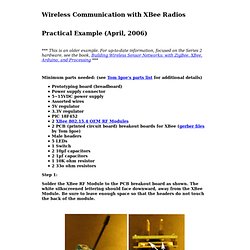
For up-to-date information, focused on the Series 2 hardware, see the book, Building Wireless Sensor Networks: with ZigBee, XBee, Arduino, and Processing *** Minimum parts needed: (see Tom Igoe's parts list for additional details) Prototyping board (breadboard) Power supply connector 5~15VDC power supply Assorted wires 5V regulator 3.3V regulator PIC 18F452 2 XBee 802.15.4 OEM RF Modules 2 PCB (printed circuit board) breakout boards for XBee (gerber files by Tom Igoe) Male headers 5 LEDs 1 Switch 2 10µf capacitors 2 1µf capacitors 1 10K ohm resistor 2 33o ohm resistors Step 1: Solder the XBee RF Module to the PCB breakout board as shown.
Temperature. Www.digi.com/standards/smart-energy/assets/appnote_xbee_se_devices.pdf. September 2011. Summary: this post explains to send remote AT commands to an XBee module using ZigBee commands.
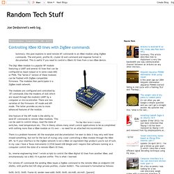
The end point, profile ID, cluster ID and command and response format is documented. This is useful if you need to control a XBee's IO lines from a non-XBee device. The Digi XBee module is a popular RF module featuring a UART and several IO lines that can be configured as input/output or in some cases ADC or PWM. The "Series 2" version of these modules can be flashed with ZigBee compatible firmware.
The modules then participate in a ZigBee mesh network. The modules are configured and controlled by AT commands (like the modems of old) which are issued through the module's UART by a computer or microcontroller. One feature of the API mode is the ability to send AT commands to remote XBee modules. There is a problem however. So, reverse engineering time!