
Neutron Shield Modulator. ArduinoSynth. This page is a meeting place for people making synthesizers and music generators with Freeduinos and Arduinos .
Code Resources for making synths and implementing analog output From a post over on the monome forums, some single chip / open source synth projects: AVR chip based designs: avrSynth - Dual oscilator, DCF, DCA, plus some LFOs. Has pins for all kinds of front panel controls, plus midi in. 1bit groovebox - full on crazy ass chip instrument, interface, sound output, the whole 9, also quite reductive in terms of sound pallette and control logic. Other chips Atmel's ATSAM2195saratronics Babblebot - synthesized speech, music, waveform synthesiscritter board OPL3 midibox Really simple project picaxe beatbox Also interesting are these PARASITE modules, small audio modules intended to be added into circuit bent hardware.
Ok, that is it for now, just wanted to get this all in my database in case the monome forum goes down. Synths made with Arduino Paul Badger's Synth Code More info at. USB Touchscreen Mouse. Code The first thing I needed to do was to make sure I could get reliable x and y position from the touchscreen before messing with the USB stuff.

Here is my project source code for just reading out the ADC values for the touchscreen. Basically, I needed two ADC readings, one for x and one for y. However, I can’t just set one pin permanently to one ADC, the pins will need to be constantly changing (refer to the chart above). I made a function for each coordinate that changes the pin assignments and takes an ADC reading. void read_x(void){ DDRC = 0b00010010; // Output on PC4(5V) and PC1(GND), Input on PC4(ADC) sbi(PORTC, 4); //pull PC4 to 5V cbi(PORTC, 1); //pull PC1 to GND _delay_ms(1); //wait for screen to initialize ADMUX = (1 << MUX1); //ADC2 ADCSRA = (1 << ADEN)|(1 << ADSC)|(1<<adps2)|(1><adps2)|(1><adps2)|(1><adps2)|(1><adps2)|(1><<adps1);><adps1);><adps1);><adps1);><adps1);> while(ADCSRA & (1 << ADSC)); l = ADCL; h = ADCH & 0x03; h = h << 8; h = h + l;}
Touch Pad (4-wire) *Some are written in English at the moment(sorry not all of them...)This example shows how to use a touch panel/screen with an Arduino board plus a serial communication to a Processing program, which draws where to touch on the touch panel.This is not about a multi-touch function, only single point on the touch panel can be detected.

今回は、4線式のタッチパネルをArduino基盤に接続し操作実験してみたいと思います。 タッチパネルには、4線式や5線式という比較的簡単な構造になっているものがあります。 今回使うタッチパネルは、指先やペン先で触れた一点の位置(X座標値とY座標値)を検出可能にするものです(複数の点を同時検出可能なマルチタッチではありません)。 基本的には、X座標に2線、Y座標に2線あり、合計4線あります。 手順としては、まずX座標を検出、そしてY座標を検出というように別々(交互)に行います。 Arduino基盤との接続は、以下のようにアナログ入力の0〜3番ピンに接続することにします(X座標用に0番ピンと1番ピン、Y座標用に2番ピンと3番ピンを使用)。 Needs a pull-down resistor for each wire from the touch panel. 処理の手順は、まずX座標(横方向)の検出を行う際には、アナログ入力の「0番ピンと1番ピン」を「14番ピンと15番ピン」としてデジタル出力に切り替え、14番ピンを0V(LOW)、15番ピンを5V(HIGH)で出力しておきます。 //デジタル出力用ピン番号の定義:the digital output pins#define xLow 14#define xHigh 15#define yLow 16#define yHigh 17.
Nintendo DS touch screen. Quite easy to do, with inexpensive components (Touch screen is 10$, break board connector 4$ and just buy it, don't be a hero), but with one or two caveats.
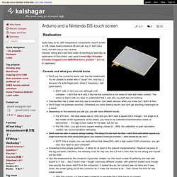
Sample, wiring and code here under. Everything is basically an application of Elm-chan's very good tutorial (but not in Japanese). Caveats and what you should know Don't buy the connector alone, just buy the breakboard, it's not posible to solder with a "usual" iron. And buy 2, because it's quite fragile and I killed 2 (hopefully I had spare parts!) Kaoss Pad Midi Controller. XY Midi Pad Controller Kits. DIY Analog Digital Synths. Arduino MIDI-in shield. The 5$ Karduinoss pad. Monome.