

Potentiometer. Comparing 2 different type of pots Size scaled 10k and 100k pots that combine traditional mountings and knob shafts with newer and smaller electrical assemblies.
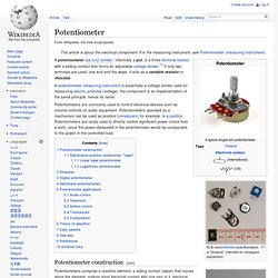
Shaft length is unrelated to resistance. Electronic symbol for pre-set potentiometer Potentiometers are commonly used to control electrical devices such as volume controls on audio equipment. Potentiometers operated by a mechanism can be used as position transducers, for example, in a joystick. Potentiometer construction[edit] Potentiometers comprise a resistive element, a sliding contact (wiper) that moves along the element, making good electrical contact with one part of it, electrical terminals at each end of the element, a mechanism that moves the wiper from one end to the other, and a housing containing the element and wiper.
Another type is the linear slider potentiometer, which has a wiper which slides along a linear element instead of rotating. The resistive element of inexpensive potentiometers is often made of graphite. Diode. Closeup of a diode, showing the square-shaped semiconductor crystal (black object on left).

Structure of a vacuum tube diode. The filament may be bare, or more commonly (as shown here), embedded within and insulated from an enclosing cathode. Main functions[edit] However, diodes can have more complicated behavior than this simple on–off action, due to their nonlinear current-voltage characteristics.
Semiconductor diodes begin conducting electricity only if a certain threshold voltage or cut-in voltage is present in the forward direction (a state in which the diode is said to be forward-biased). History[edit] Vacuum tube diodes[edit] Thomas Edison independently rediscovered the principle on February 13, 1880. Crocodile clip. Standard clip Three alligator clips: a bare standard-sized clip; a miniature clip in a yellow plastic boot; a large red Square D multi-function clip.
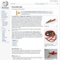
Pair of standard clips Small versions, ranging in size from 15–40 mm in length, are used in electrical laboratory work. Resistor. Axial-lead resistors on tape.
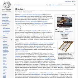
The tape is removed during assembly before the leads are formed and the part is inserted into the board. In automated assembly the leads are cut and formed. The current through a resistor is in direct proportion to the voltage across the resistor's terminals. This relationship is represented by Ohm's law: where I is the current through the conductor in units of amperes, V is the potential difference measured across the conductor in units of volts, and R is the resistance of the conductor in units of ohms (symbol: Ω). The ratio of the voltage applied across a resistor's terminals to the intensity of current in the circuit is called its resistance, and this can be assumed to be a constant (independent of the voltage) for ordinary resistors working within their ratings. Resistors are common elements of electrical networks and electronic circuits and are ubiquitous in electronic equipment.
Units[edit] . Electronic symbols and notation[edit] American-style symbols. Capacitor. 4 electrolytic capacitors of different voltages and capacitance Solid-body, resin-dipped 10 μF 35 V tantalum capacitors.
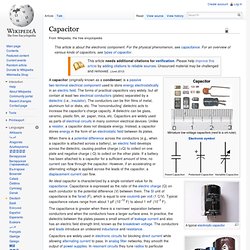
The + sign indicates the positive lead. When there is a potential difference across the conductors (e.g., when a capacitor is attached across a battery), an electric field develops across the dielectric, causing positive charge (+Q) to collect on one plate and negative charge (-Q) to collect on the other plate. If a battery has been attached to a capacitor for a sufficient amount of time, no current can flow through the capacitor.
However, if an accelerating or alternating voltage is applied across the leads of the capacitor, a displacement current can flow. An ideal capacitor is characterized by a single constant value for its capacitance. Capacitors are widely used in electronic circuits for blocking direct current while allowing alternating current to pass. History Early capacitors were also known as condensers, a term that is still occasionally used today. Overview. Photoresistor. The symbol for a photoresistor[1] A photoresistor or light-dependent resistor (LDR) or photocell is a light-controlled variable resistor.
The resistance of a photoresistor decreases with increasing incident light intensity; in other words, it exhibits photoconductivity. A photoresistor can be applied in light-sensitive detector circuits, and light- and dark-activated switching circuits. A photoresistor is made of a high resistance semiconductor. In the dark, a photoresistor can have a resistance as high as a few megaohms (MΩ), while in the light, a photoresistor can have a resistance as low as a few hundred ohms. A photoelectric device can be either intrinsic or extrinsic. The internal components of a photoelectric control for a typical American streetlight. Specification and model[edit] LDR07 CdS Light Dependent Resistor There are many types of photoresistors, with different specifications and models.
Applications[edit] Photoresistors come in many types. References[edit] See also[edit]