
Tools, Parts, Kits for DIY'ers - Curious Inventor. Bluetooth. By Mitchell Page Mpag5967 [at] mail.usyd.edu.au Key Centre of Design Computing and Cognition, University of Sydney , Australia Normally you would use a serial USB cable connected from your computer to your Wiring board for receiving data sent from a computer running processing to your board.

This tutorial demonstrates how to execute this same process, but wirelessly using Bluetooth. We will test this by being able to turn an LED on/off wirelessly. Playground - InterfacingWithHardware. These topics cover the hardware and software setup required to connect an Arduino device with a variety of electronic parts, chips and devices.

A related topic not covered under this section is the shield, boards that plug directly into an Arduino's pin layout. Information on the creation and use of specific shields belongs in that section. Information on shields in general and their creation belongs here. See here for a table of shields and the Arduino pins they use. Arduino has limits on how much current can be sourced or sunk by its I/O pins.
Navigation Output Input User interface Buttons,Encoders,Keypads Unified Input InterfaceText-based user interfacemicroBox Linux Shell look and feel for Arduino Phi_prompt user interface LibraryMenuSamplePhi_prompt glcd user interface Library This is being planned. Communication Data Logging and Plotting General Common Pinouts Examples and information for specific output devices and peripherals: How to connect and wire up devices and code to drive them. A Sensitive DIY Ultrasonic Range Sensor. I needed some ultrasonic range finders for my project.
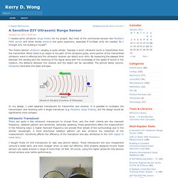
But most of the commercial sensors like Parallax’s PING sensor and other similar products are quite expensive, especially if multiple units are needed. So I thought why not building it myself? The theory behind ultrasonic ranging is quite simple. Typically a short ultrasonic burst is transmitted from the transmitter. When there is an object in the path of the ultrasonic pulse, some portion of the transmitted ultrasonic wave is reflected and the ultrasonic receiver can detect such echo. Arduino With Bluetooth, Wireless Communication Made Easy.
To establish a , you have three possibilities: XBee All of them have advantages and disadvantages. Finally, when I had to choose, I decided to go for the Bluetooth solution which, in the given circumstances, fulfilled all my requirements. Once I had choosen the wireless technology, I still had to find a shield to interface the emitter with my Arduino Uno. I Finally selected the " " from DFRobot (Ref: DFR0088). What I appreciated the most is the fact that It is possible to switch from Bluetooth to Xbee simply by swapping the emitter part, an advantage which is mostly due to the fact that the Bluetooth module has been fitted in a XBee module. The board can accommodate the three wireless technologies, through an additionnal connector. Arduino Modules-Mozilla Firefox. Arduino-tvout - A composite video output library for AVR/Arduino - Google Project Hosting-Mozilla Firefox. The goal of this project is to create a simple interupt driven library for generating composite video on a single AVR chip.
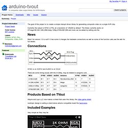
Currently the output is NTSC or PAL at a resolution of 128x96 by default. The library currently works on ATmega168,328,1280,2560,644p,1284p,AT90USB1286 and more can be added by editing one file. Beta1 for version 1.0 is out!!! It has some it changes the hardware connections as well as some of the function calls see the wiki for full details.
SYNC is on OCR1A and AUDIO is on OC2A There are some timing issues with the m1284p, may be related to sanguino core. Wayne and Layn LLC now makes a shield that uses this library, the video game shield. nootropic design is selling a stand alone arduino compatible board the hackvision. Very simple as they may be. MaterielInterfaceMoteurTB6612. MATERIEL - Interfaces – Créé le 21/01/2010.

Acheté ici ( 6 Euros TTC seulement !) : Dispo également chez Lextronic : carte de chez Sparkfun :