
Relay \ Learning. This example is for Wiring version 1.0 build 0100+.
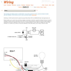
If you have a previous version, use the examples included with your software. If you see any errors or have comments, please let us know. Switching a 125VAC light bulb with a general purpose Relay Relay 5VDC by BARRAGAN Relays enable you to control one circuit from another circuit with no electronic connection between the two circuits for example to control a device (switching it ON or OFF) from the Wiring harware. A Relay is an electric switch capable of switching AC devices by applying a small current at it, making possible to control high AC voltages from the Wiring hardware. Int relayPin = 8; void setup() { pinMode(relayPin, OUTPUT); } void loop() { digitalWrite(relayPin, HIGH); delay(1000); digitalWrite(relayPin, LOW); delay(1000); }
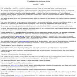
Optocoupler4N35 \ Learning. This example is for Wiring version 1.0 build 0100+.
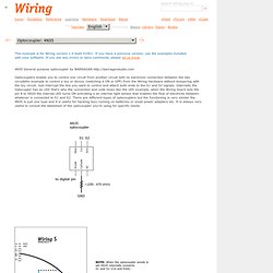
If you have a previous version, use the examples included with your software. If you see any errors or have comments, please let us know. 4N35 General purpose optocoupler by BARRAGAN Optocouplers enable you to control one circuit from another circuit with no electronic connection between the two circuitsfor example to control a toy or device (switching it ON or OFF) from the Wiring hardware without tempering with the toy circuit.
Just interrupt the line you want to control and attach both ends to the S1 and S2 signals. Playground - TLC5940. The TLC5940 is a 16 channel PWM unit with 12 bit duty cycle control (0 - 4095), 6 bit current limit control (0 - 63), and a daisy chainable serial interface.
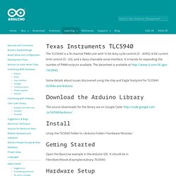
It is handy for expanding the number of PWM outputs available. The datasheet is available at Some details about issues discovered using the chip and Eagle footprint for TLC5941: tlc594x and Arduino Download the Arduino Library The source/downloads for the library are on Google Code: Install Unzip the Tlc5940 folder to <Arduino Folder>/hardware/libraries/ Part Search.
555. The Scientist and Engineer's Guide to Digital Signal Processing's Table of Content. 8 Button PC Game Controller. GoGo Board. GoGo Board: Science and Robotics for the Inventive Mind The GoGo board is a programmable device that is designed for sensor-based and control projects.
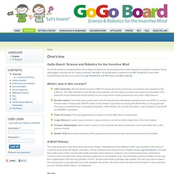
It is suited for building robots, data loggers, and devices for human-computer interaction. Its functionality is inspired by the MIT Cricket and many other programmable devices such as the the Lego Mindstorms, the IRX board, and Basic Stamps. What’s new in this version? USB Connection. A Brief History The initial designers of the GoGo Board are Arnan (Roger) Sipitakiat and Paulo Blikstein. Partfinder:ic [AdaWiki] ALLDATASHEET.COM - Datasheet search site, Datasheet search site for Electronic Components and Semiconductors and other semiconductors.-Mozilla Firefox.
Multimeters. Laser. Mes differents projets de robotique » Tutorial : Lire la position d’un servo-moteur. Moteurs. Resistances. Diodes. Adafruit Industries, Unique & fun DIY electronics and kits. .:oomlout:. Arduino & DIY Electronics and kits in the UK. Arduino High Speed Photography laser flash trigger. SCIENCES POUR TOUS Trucs et astuces de construction. Trucs et astuces de construction (difficulté: ** facile) Pour les bricoleurs, SCIENCES POUR TOUS vous propose des petits trucs et des astuces pour faciliter la construction, en vrac : - Pour fabriquer précisément des petites pièces en tôles (acier, aluminium...)
Nous réalisons le plan correspondant avec précision sur un logiciel de dessin : Autosketch, à la rigueur Paintbrush... Pour les trous circulaires de plus de 12, nous dessinons des cercles de diamètre 4 qui suivent le contour intérieur du trou. . - Pour peindre des petites pièces : nous les trempons directement dans le pot de peinture puis nous égouttons : pas de traces de pinceau, un minimum de vaisselle!
Théorie - Optocoupleur. Electronique > Théorie > Optocoupleur Dernière mise à jour : 03/11/2009 Présentation Un optocoupleur est un composant ou un ensemble de composants qui permet le transfert d'informations entre deux parties électroniques isolées l'une de l'autre d'un point de vue électrique.
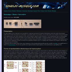
La première partie est un émetteur, et la seconde partie est un récepteur. On peut l'assimiler à un composant qui a une entrée (émetteur) et une sortie (récepteur). C328R Jpeg camera and .NET Micro Framework. One of the cool devices I wanted to get work with .NET Micro Framework was a camera.
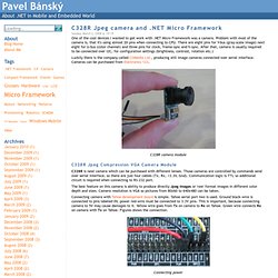
Problem with most of the camera is, that it's using almost 20 pins when connecting to CPU. There are eight pins for Y-bus (gray-scale image) next eight for U-bus (color channel) and three pins for clock, frame-sync and h-sync. After that, camera is usually required to be connected over I2C, for configuration settings (brightness, contrast, rotation etc.)
Luckily there is the company called COMedia Ltd., producing still image cameras connected over serial interface. Cameras can be purchased from Electronics 123. C328R camera module C328R Jpeg Compression VGA Camera Module C328R is neat camera which can be purchased with different lenses. The best feature on this camera is ability to produce directly Jpeg images or 'raw' format images in different color depth and sizes. Dissection of a DVD writer. Dissection of a DVD writer Ok, here is the ‘Victim’ a Sony DWD28Q 16x dual layer DVD writer And the underside: Now remove the four Philips screws & void the warranty seal ;-) Now release the left hand PCB First release the zif as shown by pushing the brown bar to the right Release the PCB retaining catch and lift the PCB upwards.

Release two more zifs on the underside of the PCB Now you can see the optical assembly (riding on the two slide rails) Now the brute force bit – detach the rails. And here is the liberated optical assy. Now is a good time to short out the diodes to prevent static damage.