[Composant] Le NE555 - Electronique - Tutoriels - Home - Page 2. The 555 Precision Timer IC - Birds on the Wire. Hello readers Today we revisit one of the most popular integrated circuits ever conceived – the 555 timer IC . “Triple-five”, “five-five-five”, “triple-nickel” … call it what you will, it has been around for thirty-eight years.
Considering the pace of change in the electronics industry, the 555 could be the constant in an ever-changing universe. But what is the 555? How does it work? What is the 555? The 555 timer is the solution to a problem found by the inventor – Hans Camenzind. Here are some examples in the common DIP casing: Furthermore a quick scan of suppliers’ websites show that the 555 is also available in surface-mount packages such as SOIC, MSOP and TSSOP. Various 555 Timer circuits - Birds on the Wire. Hello readers The purpose of this article is to follow on from our explanation of the 555 timer IC by demonstrating some simple yet interesting, noisy and plain annoying uses of the 555.
They are by no means that complex, and intended to help move theory into practice. Fire-DIY - Oscillo 555. [elettronica] circuito astabile che chiude un circuito un impulso ogni tot minuti-ore - Pagina 2. Quote: mi pare strano. se la capacità è fissata, la costante di tempo rc dovrebbe restare inalterata anche coi condensatori non elettrolitici.se la caduta di tensione che hai su r2 è maggiore di quella che hai su r1 potresti avere una polarizzazione inversa dell'elettrolitico. non dovrebbe succedere, tant'è che tutti gli esempi riportano gli elettrolitici come condensatori impiegati, però dipende dalle resistenze che usi. perché non dovrebbe?
![[elettronica] circuito astabile che chiude un circuito un impulso ogni tot minuti-ore - Pagina 2](http://cdn.pearltrees.com/s/pic/th/elettronica-circuito-astabile-12811958)
Il 555 legge due tensioni, e le confronta con due valori di riferimento. in base al confronto setta o resetta un flip flop. lo vedi qui. quando il chip viene utilizzato per un astabile, la configurazione "da libro di testo" è simile a questa: dove la tensione è quella ai capi di un condensatore, C1 che si carica attraverso la resistenza R1+R2 e si scarica attraverso La resistenza R2 per cui fissando R2 definisci il tempo necessario alla scarica ( da V_alto a V_basso) fissando R1 definisci il tempo necessario alla carica ( da V_basso a V_alto).
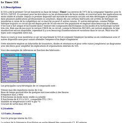
Circuits Using Ic 555 - DATASHEET and Circuit Diagram. Basic 555 timer Arduino project. I put together the arduino protoshield from sparkfun.
Excellent instructions at atomicsalad. Even though it’s a standard through-hole kit, atomicsalad’s instructions were nice to follow along. After it was put together I had a few built-in LED lights to play with. I had seen this 555 timer in a piece kit I bought and I wondered what it does. I found a ton of examples and apparently you can do a zillion things with it. I found a great tutorial on youtube and modified it to work on a larger breadboard. So here’s the schematic that I followed for the configuration on the big breadboard. I transferred this layout onto a mini breadboard and it works like a champ.
You don’t have to use the breadboard switch (the black thing on the left), it’s just more convenient to flip a switch rather than plug in/out of the 3v. Commande d'un servomoteur sans programme. Les servomoteurs sont très utilisés en robotique.

Nous leur avons consacré un grand nombre d’articles. Ce sont des modèles courants en modélisme, et ils se pilotent habituellement avec une radio-commande, donc le signal de contrôle est universel et il est possible de le reproduire avec une puce programmable, comme Eric l’a présenté dans un excellent article : Bouge ton servo Ici nous expliquons comment ne pas recourir à la programmation : on peut utiliser quelques composants électroniques simples et courants pour obtenir la commande en position d’un servomoteur. L’objectif est le suivant : ne pas implémenter dans un micro-contrôleur le signal particulier nécessaire à un servomoteur mais utiliser une carte auxiliaire prenant en entrée un niveau logique binaire (0 ou 1) pour obtenir un changement de la position du servomoteur.
Les raisons sont les suivantes, au choix : les ressources de calcul du contrôleur principal sont limitées. [Composant] Le NE555 - Electronique - Tutoriels robotique - Robotix. Un Timer simple. Le 555. Le Timer 555 1.1.Descriptions le 555 a été le premier Circuit minuterie ou base de temps ( Timer ) au environ de 1971 de la compagnie Signetics avec le SE555 / NE555 .Il convenait pour les bricoleurs ou les professionnels de façon stable, et convivial pour des applications en mono stable et astable.
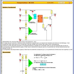
Depuis ce premier dispositif une myriade de nouveaux circuits ont étés développés et présentés dans plusieurs publications professionnels ou amateurs. depuis dix ans certains fabricants ont arrêtés de fabriquer ces minuteries à cause de la compétition sur ce marché ou pour d' autres raisons. D' autres entreprises, comme Philips fabrique toujours ce circuit qui est depuis près de 30 ans encore très populaires et employé dans beaucoup de schémas. Dans ce cours je vous montrerai ce qu' est exactement le 555 et comment l'employer lui-même ou en combinaison avec d' autres dispositifs sans pour autant atteindre l'exigence d'un degré d'ingénierie. 1.2.Symboles 1.3.Unités ; Formules t = 1,1 x R1 x C1.
NE 555. Schéma fonctionnel.
555 Contest: Welcome! 555 Timer du concours d'entrée - Le Dominoux. Winner of the 555 Timer Contest: Artistic category. www.555contest.com Winner of a Fluke Multimeter donated by 555 Timer Contest entry video: Description: Le Dominoux are “LED dominoes”, a blinking LED that propagates from device to device.