
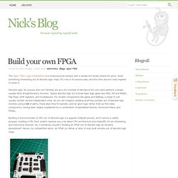
Ludde's FPGA NES. I got myself a Digilent Nexys 3 FPGA development board.
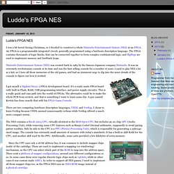
It's a ready made FPGA board with built in Flash, RAM, USB programming interface, and power supply circuitry. This is a really quick and easy path into the world of FPGAs. The alternative could be to make the whole PCB from scratch, and that is something I want to learn some day. A guy named Kevtris has done exactly that with his FPGA Game Console.There are two competing hardware description languages, VHDL and Verilog.
I chose to learn Verilog because VHDL seemed unnecessarily verbose while Verilog offered a much more compact syntax. The NES contains a Ricoh 2A03 CPU, virtually identical to the MOS 6502 CPU, but includes an on chip APU (Audio Processing Unit), while removing some CPU features such as Binary Coded Decimal arithmetic, supposedly to avoid paying patent royalties. Since the CPU uses only a 16-bit address bus, it was common to include mapper chips inside of the cartridge. These are Digilent's own expansion connectors. Low res monochrome Hitachi LCD driver - Papilio One - Gadget Factory Forum.
A friend of mine found a junked Hitachi LCD and gave it to me to see if I could get it going.
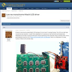
The LCD is an older type, monochrome low resolution. I couldn't find a datasheet for it or pinouts so I went old school and tracked down datasheets for the chips on board and did some reverse engineering of the schematic using a continuity meter. A very good datasheet resource is the "Hitachi LCD Controller Driver LSI Data Book" which is a compendium of a large number of Hitachi LCD controller chips.
According to the datasheet, the large chips on board are six HD61200 column shifters (IC3,4,5 and IC 6,7,8) and two HD61203 row shifters (IC 1,2). The unpopulated footprint is is a little weird with some missing pin traces (the one trace gaps on the short edge of the chip) and one less pin on one side of the chip compared to the other side. The LCD has one 20 pin set of connections that just go to the unpopulated IC11 controller chip. This project was made as the final project in a... This project was made as the final project in a class that I’m attending ( The assignement was to make a simple game on a specific hardware that was provided by our teacher.
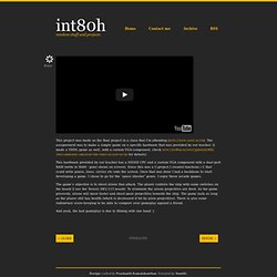
FM SOS - Hamsterworks Wiki! From Hamsterworks Wiki!
After a bit of thinking, this FPGA Project was completed in an hour in November 2012. Here is a simple FM transmitter that is surprisingly good, and very, very simple. Build your own FPGA. Posted by Nick Johnson | Filed under electronics, dfpga, open-7400 The Open 7400 Logic Competition is a crowd-sourced contest with a simple but broad criteria for entry: build something interesting out of discrete logic chips.
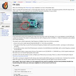
It's now in its second year, and this time around I was inspired to enter it. Discrete logic, for anyone who isn't familiar, are any of a number of families of ICs who each perform a single, usually fairly straightforward, function. Typical discrete logic ICs include basic logic gates like AND, OR and NAND, Flip-Flops, shift registers, and multiplexers. For smaller components like gates and flipflops, a single IC will usually contain several independent ones. Mandelbrot集合描画ハードウエア [Pyxis 2010] 「マンデルブロ集合をとにかく速く表示したい」との想いから、丸2年の歳月をかけた『Mandelbrot集合描画支援ハードウェア [ Pyxis ] 』が完成したのは、22年前の1988年のことです。
![Mandelbrot集合描画ハードウエア [Pyxis 2010]](http://cdn.pearltrees.com/s/pic/th/mandelbrot-pyxis-2010-42448053)
マンデルブロ集合についてはこちらへ Pyxisについてはこちらへ TTL361個を手配線で繋いだそれは、まさしくロジック回路の塊です(右写真)。 設計、製作共にとても手間暇のかかるものでしたが、当時はそれしか実現方法がありませんでした。 現在はFPGAという強力な武器があります。 Translate. Config flash - Hamsterworks Wiki! From Hamsterworks Wiki!
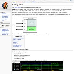
This |FPGA Project was started and finished in October 2012 Note This will not work on all FPGA boards - you have to be able to control all the required signals to the configuration flash. For example, on the Digilent Basys2 the CS line is tied to the "done" signal, so you can't enable the flash chip. Most FPGA boards include a serial Flash chip to hold the configuration bitstream, which the FPGA loads on power up.
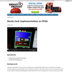
This flash is almost always larger than the FPGA needs. You can use the excess capacity to store your own data - here's how to do it. Reading from the flash On the Papilio One, read requires Dropping the CS line Sending the read command (0x03) Sending a 24 bit address, Clocking out the data. Here is the waveform from the simulator, reading from address 0x2C000: BombJack. 3/May/2012 Author: Alex Quicklinks Background.
All Programmable Technologies from Xilinx Inc. Interfacing a PC graphics card (Radeon HD 2400) with a STM32 microcontroller. TKJ Electronics » LVDS Display controller for microprocessors. We have had a couple of embedded projects for our customers where the requirement were large-screen LVDS displays.
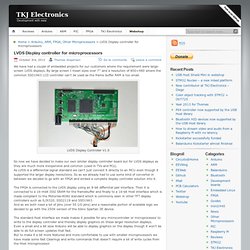
By large screen I mean sizes over 7″ and a resolution of 800×480 where the common SSD1963 LCD controller can’t be used as the frame buffer RAM is too small. LVDS Display Controller V1.0 So now we have decided to make our own similar display controller board but for LVDS displays as they are much more inexpensive and common (used in TVs and PCs).As LVDS is a differential signal standard we can’t just connect it directly to an MCU even though it supported the larger display resolutions. So as we already had to use some kind of converter in between we decided to go with an FPGA and embed a complete display controller solution into it.
The FPGA is connected to the LVDS display using an 8-bit differntial pair interface. So currently the display controller supports the following commands: MbedConsole. Well, I think I should finally document how to actually build the MbedConsole.
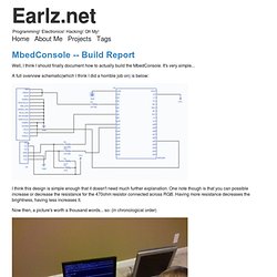
It's very simple... FPGA Logic Cells. Lately I've seen lots of homebrew CPUs mentioned in blogs and videos, but not too much about homebrew FPGAs. Did a little digging (mostly on Wikipedia), and was able to breadboard a basic logic cell circuit. Here's how I did it. Dx display - Hamsterworks Wiki! From Hamsterworks Wiki! This FPGA Project was completed in September 2012. This project lights one segment in each display, and turns all the LEDS on. The board is a TM1638 display board from Deal Extreme ( The only documentation I had available to me was - an Arduino Library in C++. Tested on a Digilent Nexys2 at both 5V and 3.3V VCC, and the Digilent Basys2 at 3.3V, with transfers slightly under 1MHz.
4-bit ALU - Demonstration, Schematics. All and all, the ALU was actually less time consuming that I had feared. It still took an annoyingly long time, but I had a bunch of free time the past 2 days and really wanted to get it done. I had a nice setup with Chappelle's show and Star Trek TNG alternating on my computer that made it a lot easier. Below are the schematics detailing which gate is where on the breadboard and which switch does what. I also numbered the wires according to the variable names for the connections in the hdl code I posted earlier. I was not in the mood to write down all those wires on this schematic, and saw no point as the connections were detailed in the hdl code, so I didn't. Pwdr - Open source powder-based rapid prototyping machine. Adding Serial Pattern Trigger feature to LOGICPORT - EECS Projects.
Bucket-brigade device. A bucket brigade or bucket-brigade device (BBD) is a discrete-time analogue delay line,[1] developed in 1969 by F. Sangster and K. Teer of the Philips Research Labs. It consists of a series of capacitance sections C0 to Cn. The stored analogue signal is moved along the line of capacitors, one step at each clock cycle. The name comes from analogy with the term bucket brigade, used for a line of people passing buckets of water. In most signal processing applications, bucket brigades have been replaced by devices that use digital signal processing, manipulating samples in digital form.
Charge-coupled device. A specially developed CCD used for ultraviolet imaging in a wire-bonded package A charge-coupled device (CCD) is a device for the movement of electrical charge, usually from within the device to an area where the charge can be manipulated, for example conversion into a digital value. This is achieved by "shifting" the signals between stages within the device one at a time. CCDs move charge between capacitive bins in the device, with the shift allowing for the transfer of charge between bins. Moving Picture Experts Group. MPEG logo Sub Groups[edit] ISO/IEC JTC1/SC29/WG11 – Coding of moving pictures and audio has following Sub Groups (SG):[6] RequirementsSystemsVideoAudio3D Graphics CompressionTestCommunication Cooperation with other groups[edit] Joint Video Team[edit]
Computer vision. Computer vision is a field that includes methods for acquiring, processing, analyzing, and understanding images and, in general, high-dimensional data from the real world in order to produce numerical or symbolic information, e.g., in the forms of decisions.[1][2][3][4] A theme in the development of this field has been to duplicate the abilities of human vision by electronically perceiving and understanding an image.[5] This image understanding can be seen as the disentangling of symbolic information from image data using models constructed with the aid of geometry, physics, statistics, and learning theory.[6] Computer vision has also been described as the enterprise of automating and integrating a wide range of processes and representations for vision perception.[7] As a scientific discipline, computer vision is concerned with the theory behind artificial systems that extract information from images.
Integrating Vision Toolkit. LinuxMCE. ShiftPWM support topic. Latest update: Schematics, high power LED's, LED strips. Update August 9 2012:I finally had the time to completely rewrite the documentation. You can now find schematics for normal RGB LED's, LED strips and high power LED's on www.elcojacobs.com/shiftpwm. 595 Shift Register Simulator.
For beginners, the 595 series Shift Register isn’t easy to grasp. I’ve written an interactive 595 simulator so you can learn out the 595 works without having to wire one together. New Furnace with Heat exchanger (Pic heavy) I have already started w3, reason for this thread :P . How to build a DIY perpetually-powered wireless outpost. Earlier this week, I had a mystery box of electronics and was looking for something to do with it. DIY Copper Vapor Laser. Brainfuck beware: JavaScript is after you! Build A CPLD Dev Board - Introduction. May 2012. S DevBlog - Electronics Engineering, Free circuits, Programming Resources, Web Development. Dvid test - Hamsterworks Wiki! Pipistrello - Hamsterworks Wiki! FPGA DC Motor Control - Data. Maxim PMOD family speeds FPGA design : Media & Entertainment Technology. Memristor.
Translate. FPGA CPLD and ASIC from Altera. FPGA. FPGA MIDI Synth update: MIDI improvements, Polyphony, PWM etc - Michael Duerinckx. Checkmate! RUB researchers outsmart copy protection HDCP. UClinux - Hamsterworks Wiki! Python Hardware Processor. An Editor for HDLs. Undiscovered Features: Space Invaders - 2 Player. Evolutionary algorithms and analog electronic circuits.
PSP Screen - eStuffz. TFT_LCD LQ043T3DX02 English. LCD Controller - How to control a laptop LCD panel with an FPGA. ROV. A Commodore Pet in an FPGA. Surveillance Module - LVL1. Free range factory Main/Home Page. Digital Signal Processing with FPGAs.