
Journal - GPS Clock using an Arduino Micro. Shrimp / Arduino. The Shrimp is a low-cost Arduino-compatible, microcontroller circuit that can be made for £3 - £4 (depending on how and where you source your components) and which can then be used to create digital inventions.
The Shrimp has been devised by Cefn Hoile at Shrimping.it for use in 'maker' workshops in Morecambe, the shrimping capital of England. For those of you who don't know what an Arduino is, it's a single-board microcontroller based on the Atmel ATMEGA series of chips with a software suite for programming it. Compared to other similar micro-controller boards such as the BASIC Stamp, the Arduino is much cheaper as well as having fully open hardware and open source software.
The latest Arduino board is the Uno R3 (shown above) which uses the ATMEGA328 microcontroller chip. Although it's available as prefabricated circuit board, there is even a breadboard version of the Arduino which can be self-assembled. Optional components: Phduino - pH meter using Arduino board for glass electrode. This project describes an open software open hardware pH meter using an Arduino/Freeduino board.
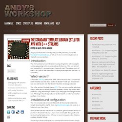
In other words, this is an electronic circuit to be connected with a glass electrode pH sensor. It was possible by the idea from my friend Mr. The Standard Template Library (STL) for AVR with C++ streams. Yes you did read that correctly, this post will present a port of the Standard Template Library, or STL as it’s more commonly known, to the AVR microcontrollers.
Introduction. Nokia QVGA TFT LCD for the Arduino Mega. Design and build (part 1 of 2) In two of my previous articles I showed you how to reverse engineer the Nokia 2730 LCD for connecting to a device with 3.3V I/O’s and then I showed you how to build a 16-channel level converter for connecting devices together that have differing I/O level requirements.
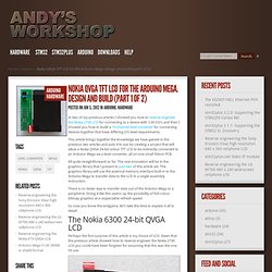
This article brings together the knowledge we have gained in the previous two articles and puts it to use by creating a project that will allow a Nokia QVGA 24-bit colour TFT LCD to be indirectly connected to an Arduino Mega via a level converter, all on one small 50mm PCB. All quite straightforward so far. Nokia QVGA TFT LCD for the Arduino Mega. Graphics Library (part 2 of 2) In part 1 of this two part series I presented the hardware design and build for the Nokia 6300 TFT that shows how we can connect it directly to the external memory interface of the Arduino Mega and that by doing so we achieve the fastest possible interface between the TFT and the Arduino MCU.

Servo101. Servos have a 3 pin connector, consisting of ground, supply voltage, and control signal.
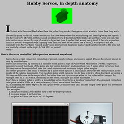
Pinouts have been known to vary by manufacturer. Servos are controlled by sending it a variable width pulse (a type of Pulse Width Modulation (PWM)). Important paramiters about the shape of the pulse are the 'centre duration' and repetition rate. A servo often turns less than 180 degrees on the output shaft over the rated minimum and maximum output pulse lengths. Arduino wisdom and gems by Mikal Hart.
Arduino ControlWare v.1.0 Beta. I had a bit of an experience developing GUI`s and Data Visualization in Processing.Processing is very cool to work with and the designs are highly scale-able.
There are tons and tons of separate examples and libraries available for processing especially the Serial Library which eases the task. During this week , i tried to make myself a GUI using Visual C#. It was a really great experience.Although you can make buttons in processing too..but its a lot easier in Visual C# Express.However, it seems not many DIY`ers use C# and its used mainly by hardcore coders and developers..but still i managed to find some cool references via MSDN and a demo(of his work) by my friend to put together a simple and easy way to talk to Arduino on a windows machine! You can monitor Analog Inputs , control digital pins and connect to the COM Port of your choice.Since i am still building upon it.So i am leaving a gist of how the GUI/program currently looks.
You will see that the Digital Pin 13 is missing. Current local time in Germany – Berlin – Berlin. Taking Arduino to the next level with AVR-GCC: part 3. In part 1, we examined the architecture of the Arduino and AVR microcontroller.In part 2, we set up the AVR-GCC toolchain and avrdude.
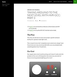
The Plan This time, we will look at some more project-specific hardware buildup for a gradual-wake light clock. This is meant to be at the “completely new to electronics design” level. If you know your way around parallel LEDs, you can probably build something better than I’ll build here. Our Goal Our regular alarm clock is pretty jarring, and it doesn’t really solve the problem of the room still being dark. Our little dream (or dream-interrupting) device. Obviously the real thing will be nowhere near as pretty, but it gives us an idea of what hardware and software components we will need: Arduino Uno and Arduino Mega Support from Simulink. Emulare - Arduino Emulator. Little Bird Electronics. Arduino as a Pic18F programmer - High Spark. So I get my hand on a PIC18F2550.Unfortunately I don't have a PIC programmer, and I'm reluctant to build a parallel/printer port programmer, so I made one using my Arduino.
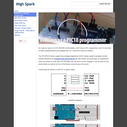
The PIC18F2/4 family support low-voltage programmer which makes easier to program via the Arduino.Moreover the programming specifications are well written and quite easy to understand.I wrote my sketch to work with PIC18F2550 only, but with a minor changes it can be work for the whole family as well (a full list of the family can be found at the end). Connecting the arduino to the PIC is quite simple: Traduction. Sensor smoothing and optimised maths on the Arduino - Alan's Ramblings. As part of my attempt to load as much as possible onto an Arduino, I added a LIS302DL accelerometer into the mix and used the Y axis output to drive a strip of LEDs via a couple of TLC5916 LED drivers. I was sampling the accelerometer every 10msec and it jittered a little, so I wanted to add some smoothing to the sensor values.
There are all sorts of fancy smoothing algorithms available, but a simple Exponential moving average worked just fine, and was easy to calculate: // choose a weighting factor W between 0 .. 1, then // current average = (current sensor value * W) + (last average * (1 - W)) static uint16_t avg = 0; uint8_t val = getAccelValue(); avg = val * 0.1 + avg * 0.9; All well and good, the maths is simple and everything works fine. Bald Wisdom » Blog Archive » BootDrive for Arduino. Announcing the formal release of BootDrive for Arduino. Androino! Control an Arduino from your Android device using a cheap bluetooth module. Tutorials. Jleblanc. 12.9.06: XBees go solo and sleep on the job I go over the basics of getting an XBee to run by itself and sleep.
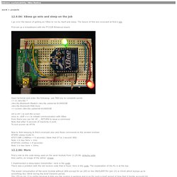
The basics of this are coveraed at Rob's site First set up a breadboard with the FT232R Breakout board. Open terminal and enter the following: use TAB key to complete words >> ls /dev/tty.* /dev/tty.Bluetooth-Modem /dev/tty.usbserial-A1000S5B /dev/tty.Bluetooth-PDA-Sync >> screen /dev/tty.usbserial-A1000S5B ctrl a ctrl \ to exit the screen once in: shift +++ to initiate communication with XBee from there you can hit: AT__ RETURN to issue a command Note that after 5 seconds of inactivity it exits To exit sooner do ATCN Now to Add sleeping to Rob's example also add these commands to the sended module: ATSM5 (sleep mode 5) ATST1388 (1388hex = 5 seconds) (Note that GT is 1 second 3E8) Note 1 in hex here = 1ms ATSP320 (320hex = 8 seconds) Note 1 in hex here = 10ms 12.2.06: More First a link to the code being used on the send module from 11.29.06: arduino code.
Rob Faludi. Arduino Tutorials. Playground - RegulatedPositiveVoltageBooster. Outputs 1/4 Watt, up to +60V DC Max Accepts any input voltage (1V minimum) Uses a simple, flexible circuit Warning: If you don't follow the instructions carefully, wiring this circuit wrong can damage your Arduino.
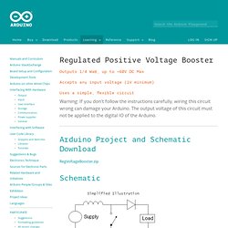
The output voltage of this circuit must not be applied to the digital IO of the Arduino. Arduino Project and Schematic Download RegVoltageBooster.zip Schematic Pictures. ELECTRONICS - THE KING OF HOBBIES!: Playing video on nokia color LCD using an 8 bit AVR! [atmega32] Code, circuits, & construction. A stepper motor is a motor controlled by a series of electromagnetic coils. The center shaft has a series of magnets mounted on it, and the coils surrounding the shaft are alternately given current or not, creating magnetic fields which repulse or attract the magnets on the shaft, causing the motor to rotate.
This design allows for very precise control of the motor: by proper pulsing, it can be turned in very accurate steps of set degree increments (for example, two-degree increments, half-degree increments, etc.). They are used in printers, disk drives, and other devices where precise positioning of the motor is necessary. There are two basic types of stepper motors, unipolar steppers and bipolar steppers. Birds on the Wire - Birds on the Wire is the Little Bird Electronics blog. Fuzzy Logic Tutorial - An Introduction. Tutorial: Analog input for multiple buttons – Part Two - Birds on the Wire.
{*style:<b><i> Welcome back fellow arduidans! </i></b>*} A while back I described how to read multiple buttons using only one analog input pin. However we could only read one button at a time.