
CD00116930.pdf (application/pdf-Objekt) Buck-boot-application-note.pdf (application/pdf-Objekt) 12 Volt AC to DC Power Supply Circuit. The schematic diagram below shows a simple trivial low-cost 12 volt DC 50W off-line SMPS switching power supply circuit.
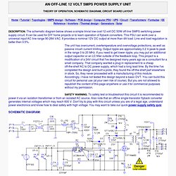
It can be used for DIY home projects or to learn operation of flyback converters. This PSU can work over a universal input AC line range 90-264 VAC. It provides a nominal 12V DC output at more than 4A load. Line and load regulation is better then 0.5%. The unit has overcurrent, overtemperature and overvoltage protections, as well as passive inrush current limiting. To safely test or troubleshoot this circuit it is recommended to power it via an isolation transformer or from an isolated AC source. This AC to DC power supply utilizes a flyback, which is the simplest SMPS converter topology. 250 W S.M.P.S. mit Power-FETs. 250 W S.M.P.S. mit Power-FETs Sicherheitshinweis Achtung Lebensgefahr: Die nachfolgende Schaltung arbeitet am 230 VAC Wechselstromnetz.
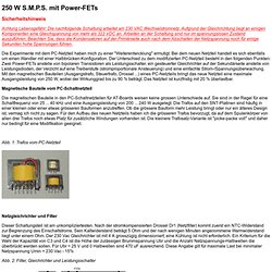
Aufgrund der Gleichrichtung liegt an einigen Komponenten eine Gleichspannung von mehr als 322 VDC an. Arbeiten an der Schaltung sind nur im spannungslosen Zustand auszuführen. Beachten Sie, dass die Kondensatoren auf der Primärseite auch nach dem Abschalten der Netzspannung noch für einige Sekunden hohe Spannungen führen. Die Experimente mit dem PC-Netzteil haben mich zu einer "Weiterentwicklung" ermutigt. Design of switch power supplies. A Half Bridge Buck Boost Converter with high side N-type MOSFET. The buck-boost converter is of value where the output and/or input voltages vary to such an extent that on occasions a buck converter is needed, while on other occasions a boost converter is needed.
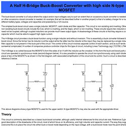
An example (that will be described further in another project) is that of a battery charger for a number of different battery types, voltages and capacities and powered by a 12V source. The simplest buck-boost circuit uses a single inductor, MOSFET, catch diode and filter capacitor. This circuit is non-isolating and inverting. Other non-isolating buck-boost circuits include the Ćuk, which is inverting, and the Sepic, which is non-inverting. These circuits require two inductors which need not be coupled, although coupled inductors can provide much lower output ripple.
The H-Bridge circuit provides a buck-boost function using a single inductor and without inversion. The H-Bridge is so called because the MOSFETs form the sides of an H with the inductor as the crossbar. Theory Experiment. Paper21.pdf (application/pdf-Objekt) AN1661-D.PDF (application/pdf-Objekt) Simple Circuit Diagram. One AC-DC converter that provides a good accuracy is SMPS AC-DC converter.
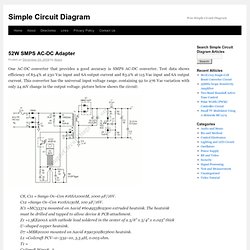
Test data shows efficiency of 85.4% at 230 Vac input and 6A output current and 83.2% at 115 Vac input and 6A output current. This converter has the universal input voltage range. containing 92 to 276 Vac variation with only 24 mV change in the output voltage. picture below shows the circuit: C8, C11 = Sanyo Os–Con #16SA1000M, 1000 µF/16V. C12 =Sanyo Os–Con #10SA150M, 100 µF/16V. IC1 =MC33374 mounted on Aavid #604953B02500 extruded heatsink. Slyt391.pdf (application/pdf-Objekt) DSA0019335 datasheets and application notes, data sheet, circuit, pdf, cross reference, pinout, datasheet.
How to power up a smps for the first time. Hello friends.
I am new, and although I have experience in electronics, I am quite ignorant about SMPS and I am starting from scratch. So any wise suggestions are going to be very welcome. I decided to start a project. I thought the simplest was using PI Expert software from Power Integrations to do what I really don't know which is calculating and building a SMPS transformer. The software gives almost every detail, from the schematic to the PCB when you select one of the PI chips. I choose a 24 V @ 10 A rating for the output, and 175 to 265 VAC for mains because we have 220 VAC in my country.
I am good drawing PCB's , so I ordered some boards following the manufacturer;s indications. In the meantime there is something that worries me, this is how to power up this SMPS considering some things such as the core gap. So, my question is: is there any more or less failsafe procedure to power-up this circuit ? Tutorials/info on SMPS,DC-DC converters. AVR Freaks General Electronics - Tutorials/info on SMPS,DC-DC converters npat_avr - May 07, 2009 - 02:26 AMPost subject: Tutorials/info on SMPS,DC-DC converters Hi Guys, Does anybody know any good tutorials/links on designing and testing high power SMPS and DC-DC Converters?
An25fa.pdf (application/pdf-Objekt)