
Sparx Systems - UML 2 Tutorial - Sequence Diagram. Sequence Diagrams A sequence diagram is a form of interaction diagram which shows objects as lifelines running down the page, with their interactions over time represented as messages drawn as arrows from the source lifeline to the target lifeline.
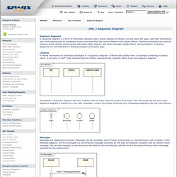
Sequence diagrams are good at showing which objects communicate with which other objects; and what messages trigger those communications. Sequence diagrams are not intended for showing complex procedural logic. Lifelines A lifeline represents an individual participant in a sequence diagram. A lifeline will usually have a rectangle containing its object name. Introduction to the Diagrams of UML 2.0. Introduction to UML 2 Sequence Diagrams. Sequence diagrams are typically used to model: Usage scenarios.
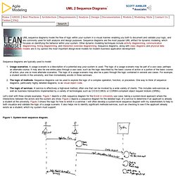
A usage scenario is a description of a potential way your system is used. The logic of a usage scenario may be part of a use case, perhaps an alternate course. It may also be one entire pass through a use case, such as the logic described by the basic course of action or a portion of the basic course of action, plus one or more alternate scenarios.
The logic of a usage scenario may also be a pass through the logic contained in several use cases. Let's start with three simple examples. Figure 1. The reason why they're called sequence diagrams should be obvious: the sequential nature of the logic is shown via the ordering of the messages (the horizontal arrows). Figure 2. The boxes across the top of the diagram represent classifiers or their instances, typically use cases, objects, classes, or actors. UML basics: The sequence diagram. UML basics Donald BellPublished on February 16, 2004 It's February, and by now you've probably read about, or heard people talk about, making the change to UML 2.0--the new specification for UML that contains a number of improvements.
Given the importance of the new spec, we are changing the basis of this article series, too, shifting our attention from OMG's UML 1.4 Specification to OMG's Adopted 2.0 Draft Specification of UML (a.k.a. UML 2). I hate to change emphasis from 1.4 to 2.0 in the middle of a series of articles, but the UML 2.0 Draft Specification is an important step forward, and I feel the need to spread the word. Sequence diagram. Sequence diagram of e-mail message sequence A sequence diagram is an interaction diagram that shows how processes operate with one another and in what order.
It is a construct of a Message Sequence Chart. A sequence diagram shows object interactions arranged in time sequence. It depicts the objects and classes involved in the scenario and the sequence of messages exchanged between the objects needed to carry out the functionality of the scenario. Sequence diagrams are typically associated with use case realizations in the Logical View of the system under development. A sequence diagram shows, as parallel vertical lines (lifelines), different processes or objects that live simultaneously, and, as horizontal arrows, the messages exchanged between them, in the order in which they occur.
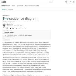
Diagram building blocks[edit] UML Sequence Diagrams : A Quick Introduction. UML sequence diagrams are used to show how objects interact in a given situation. An important characteristic of a sequence diagram is that time passes from top to bottom : the interaction starts near the top of the diagram and ends at the bottom (i.e. Lower equals Later). A popular use for them is to document the dynamics in an object-oriented system. For each key collaboration, diagrams are created that show how objects interact in various representative scenarios for that collaboration. The UML sequence diagram gallery contains many examples, but here's a typical sequence diagram based on a system use case scenario : The diagram above shows how objects interact in the "rent item" collaboration when the item is not available during the requested period. To clarify how execution switches from one object to another, a blue highlight was added to represent the flow of control.
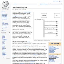
As with all UML diagrams, comments are shown in a rectangle with a folded-over corner : Object MultiObject Class. Uml - How to show "if" condition on a sequence diagram. Describing Control Flow with Fragments in UML Sequence Diagrams. In a UML sequence diagram, combined fragments let you show loops, branches, and other alternatives.
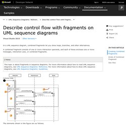
A combined fragment consists of one or more interaction operands, and each of these encloses one or more messages, interaction uses, or combined fragments. The elements shown in the figure are as follows. A combined fragment. There are several kinds of combined fragments. This example is an Alt combined fragment, which you can use to show that alternative sequences of messages can occur.Interaction operands. Sequence diagram.