
Arduino Modules - Rain Sensor : 4 Steps. Open Weather Station - the arduino open source weather station. The Open Weather Station (OWS) is a do-it-yourself weather station solution that aims to be affordable, stable, easy to build and tested in the wild.
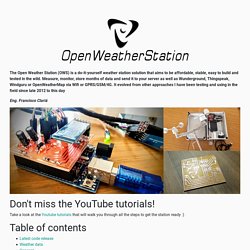
Measure, monitor, store months of data and send it to your server as well as Wunderground, Thingspeak, Windguru or OpenWeatherMap via Wifi or GPRS/GSM/4G. It evolved from other approaches I have been testing and using in the field since late 2012 to this day Eng. Francisco Clariá Take a look at the Youtube tutorials that will walk you through all the steps to get the station ready :) Access the latest stable release from here (recommended): Production ready sources To access the most up-to-date (yet not fully tested) project version access the develop branch here: Current source code The Open Weather Station App (Android only) is ready for use for free just install it from the Google Play as any other app.
The information generated by the OWS every minute is the following: Next you can read more about the concepts behind this implementation. Node-RED. OLD: Version 5 of Single Channel LoRa Gateway.
Arduino. DHT22 High Accuracy Humidity and Temperature Sensor. Home.utad.pt/~digital2/Apoio/Software/Sensores/Sensor_Humidade.pdf. Capacitance Measurer v1.0. Question: is measurer a real word?
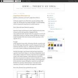
- google doesn't think so. I, like many people I'm sure, find certain capacitor markings a little cryptic. So, with the help of my Arduino Decimilla, I set about building a device to measure the capacitance of a selected capacitor. First, a little of the theory behind its operation: Capacitors charge and discharge at certain 'speeds' based on the series resistance and its total capacitance. Example:100uF capacitor in series with a 10K resistor will take 1 second to reach 63.2% of full charge, then another 1 second to charge up to 63.2% of the remaining capacitance and so on... With this knowledge, I may be able to time how long it took for the capacitor to reach 63.2% charge, or, since they are proportional, 63.2% of the arduino's voltage level. Here is the schematic I have produced for my circuit: NOTE: Sorry, I've just noticed I missed out 3 of the PWM pins on the Arduino.
The switch 'S1' is used to start the measurement. Now, here's the code: Chris. Blog » ATTiny45. ELM - DC Servomotor Controller. This is an experiment on the closed loop DC servomotor control system (SMC). It will able to be used for practical use with/without some modifications. The closed loop servo mechanism requires real-time servo operations, such as position control, velocity control and torque control.
It will be suitable for implementation to any embedded 32 bit RISC processors as a middleware. In this project, these operations are processed with only a cheap 8 bit microcontroller. Recently, most servo systems are using brushless motors called "AC servo motor" to reduce maintanance cost. Hardware Figure 1. Figure 2. Figure 1 shows the block diagram for SMC. Figure 2 shows the circuit diagram for SMC. JP1 is an ISP connector to program the AVR, and it can also used to attach an LED display board. Options. You might also want to look at Resources .
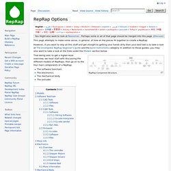
Perhaps some or all of that page should be merged into this page. (Discuss) This page attempts to make some sense, in general, of how all the pieces fit together to create a RepRap. However, if you want to skip all this stuff and get straight to getting your hands dirty then your best bet is to take a look at The incomplete RepRap beginner's guide and the build instructions category.
In addition to those guides, you may also want to take a look at the links under the Models section below. RepRap Component Structure. That being said, to get a higher-level overview, we must start with discussing the different models of RepRaps, then go on to the four main components of a RepRap: The software toolchain. Models These days there are a growing number of many great and detailed build instructions for RepRaps!
If you're steampunk or just like to get away without commercial kits, there are also RepStraps. Software Toolchain CAD tools. CAD Tools Software Files. Improved Analog & Digital Interface with Arduino. « Analog inputs with Arduino and EMC | Newest entries | Generating HAL files from Eagle schematics » Building on my earlier work , I've now improved the interface between HAL and the Arduino board to have: 6 10-bit analog inputs 6 8-bit PWM "analog" outputs 6 digital inputs/outputs (partition chosen when component is loaded) GPL license statement in source files As before, the driver consists of an Arduino Sketch ( halintf.pde ) and a HAL Userspace Component written in Python ( arduino.py ).
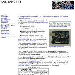
First, load the sketch (firmware source code file) in the Arduino GUI, compile it, and transfer it to the board.