Input/Output Expansion With An Arduino - Let's Make It - Episode 31 - Tech-Zen.tv - Alixa.tv. Decoder for 128 outputs. Expanding the number of I/O lines using Microchip MCP23008. A microcontroller comes with a limited number of general purpose input and output (GPIO) ports.
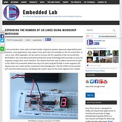
However, some applications may require more ports than are available on the microcontroller. In such a case, GPIO expanders can be used to increase the I/O capability of the microcontroller. MCP23008 is one such device (manufactured by Microchip Technology) which provides an easy I/O expansion using 2-wire serial interface. This tutorial illustrates how to add an extra 8-bit I/O port to PIC12683 microcontroller (which has only 6 I/O pins) using MCP23008.
A seven segment LED display and a tact switch will be connected to the extended port. MCP23008 port expander interfaced to PIC12F683 Theory The MCP23008 an I2C slave device that provides 8-bit, general purpose, bi-directional I/O expansion for I2C bus. I2C control byte format for MCP23008 Control and configuration registers The individual bits of the 8-bit GPIO port can be configured as input or output. Configuration and Control registers. EXPAND Shift Register / Expansion Module Quickstart Guide. The Shift Register / Expansion Module uses a 74HC595 shift register to allow you to drive 8 output channels using 3 pins on your microcontroller.
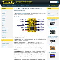
Module Pinout Serial OUT: Passes serial data back out to another module. Can be connected to the Serial IN of another module to daisy-chain them together and control even more outputs. Typically left unconnected. Serial IN: Data sent from the microcontroller to set the state of the output pins. Latch: Also sometimes referred to as the "storage clock" or "latch clock". Clock: On a LOW-to-HIGH transition this pin causes the value currently applied to the Serial IN pin to be read into the shift register, and all other values moved along one position. Output Enable: Active LOW. Reset: Active LOW. GND: Connect to GND (0V) on your microcontroller. VCC: Connect to 5V on your microcontroller. Outputs A-H: Outputs to your other devices. Basic Usage We've also connected: Maximising your Arduino's I/O ports with MCP23017.
This is chapter forty-one of a series originally titled “Getting Started/Moving Forward with Arduino!”
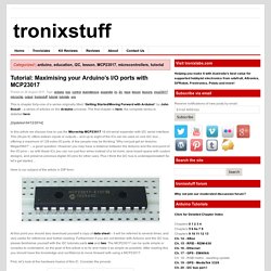
By John Boxall – a series of articles on the Arduino universe. The first chapter is here, the complete series is detailed here. [Updated 04/12/2014] In this article we discuss how to use the Microchip MCP23017 16-bit serial expander with I2C serial interface. This 28-pin IC offers sixteen inputs or outputs – and up to eight of the ICs can be used on one I2C bus… offering a maximum of 128 extra I/O ports. Here is our subject of the article in DIP form: At this point you should also download yourself a copy of data sheet – it will be referred to several times, and very useful for reference and further reading. First, let’s look at the hardware basics of this IC. The sixteen I/O ports are separated into two ‘ports’ – A (on the right) and B (on the left. Finally we have the three hardware address pins 15~17. Tutorial – 74HC4067 16-Channel Analog Multiplexer Demultiplexer. Introduction Now and again there’s a need to expand the I/O capabilities of your chosen micorocontroller, and instead of upgrading you can often use external parts to help solve the problem.
One example of this is the 74HC4067 16-channel analog multiplexer demultiplexer. That’s a mouthful – however in simple form it’s an IC that can direct a flow of current in either direction from one pin to any one of sixteen pins. Another way to think abou it is that you can consider the 74HC4067 to be a digital replacement to those rotary switches that allow you to select one of sixteen positions. Here’s an example of the SMD version: Don’t let that put you off, it’s just what we had in stock at the time.
Using the 74HC4067 At this point you should download the data sheet, as we refer to it through the course of the article. The power supply for the part is applied to pin 24, and GND to … pin 12. Next – pin one. Limitations Examples Now to show an example of both multiplexing and demultiplexing.