
Tkinter - python code for serial data to print on window. PROTEUS - The Complete Electronics Design System. Supported Third Party Compilers All Proteus VSM processor models are able to run binary files (i.e.
Intel or Motorola Hex files) produced by any assembler or compiler. However, the debugging facilities available are very limited since the processor model has no way to correlate the machine code it is executing with your original source program. Fortunately, most compilers also produce symbolic debug data files that contain extra information to be used by debuggers and other tools. The Proteus VSM processor models are able to load the debug data files produced by selected third party compilers enabling them to provide full high-level language debugging facilities including the ability to display and step through the original source code as well as display the contents of program variables as the code executes. For AVR or ARM development we recommend using the ELF/DWARF debug format if such is available as debug output from within your compiler.
Proton Development Suite Bascom AVR IAR Systems. Google Translate. Circuit simulation in LTSpice part 3/3. Circuit simulation in LTSpice part 2/3. Circuit simulation in LTSpice part 1/3. Circuit Simulator Applet. This is an electronic circuit simulator.
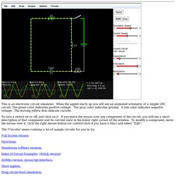
When the applet starts up you will see an animated schematic of a simple LRC circuit. The green color indicates positive voltage. The gray color indicates ground. A red color indicates negative voltage. The moving yellow dots indicate current. To turn a switch on or off, just click on it. The "Circuits" menu contains a lot of sample circuits for you to try. Full Screen version. Subcircuits Page. Device Models, & Subcircuits 10-BIT-DAC-BEH.zip 10-BIT DAC (Behavioral) Subcircuit (with PSpice & LTspice Symbols) When you are designing a system at the device level (transistors, resistors, etc.), it's convenient (and speedy) to represent some subsystems behaviorally while you wring out other system components, e.g. a successive approximation register.
MOrcad speaker/crossover simulation page. OrCAD Downloads. OrCAD 16.6 Lite Demo Software (All Products) Designers around the world rely on the powerful yet intuitive OrCAD® personal productivity tools.
OrCAD has a long history of providing individuals and teams with a complete set of technologies that offer unprecedented productivity, seamless tool integration, and exceptional value—the OrCAD 16.6 release continues with that tradition. The OrCAD 16.6 demo software will let you experience all the features and functionality of the actual software*. So go ahead, discover how easy it is to use these state-of-the-art OrCAD technologies. * Limitations are in the size and complexity of the design. The OrCAD Lite download includes demo versions of the following tools: OrCAD Capture, OrCAD Capture CIS, PSpice® A/D, PSpice Advanced Analysis, OrCAD PCB and SPECCTRA® for OrCAD.
SPICE Circuit Components. SPICE - a brief overview. This document gives a brief overview of SPICE.
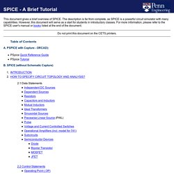
The description is far from complete, as SPICE is a powerful circuit simulator with many capabilities. However, this document will serve as a start for students in introductory classes. Spice Circuit Simulation. Untitled Document. The objective of this webpage is to further demonstrate the different modes of operation of a typical BJT Inverter.
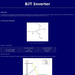
Through simulation tools such as PSpice and MoHAT as well as through the analytical method, we will find the critical voltages of the BJT Inverter (VOH, VIH, VOL, VIL). Figure 1: Schematic of typical BJT Inverter The critical values of a typical BJT Inverter cab be retrieved from it's Voltage Transfer Characteristic graph (VTC) like in Figure 2. Figure 2: VTC of BJT Inverter Following the VTC, we can obtain the critical values of the inverter: PSpice Tutorials. Getting Started With Proteus. Hello readers, today’s post is the first regular post on Proteus tutorial.
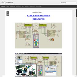
Today’s tutorial is for beginners who don’t have much knowledge of Proteus but wants to start working with it. We don’t design any circuit in today’s post instead we will check the different functions of Proteus which provides ease in circuit designing. Proteus has different functions in it and in order to design a circuit, one must have sound knowledge of each of them. I have divided this tutorial in ten parts and today we will discuss the first part of this tutorial. ISIS PROTEUS. Download; PC IR remote control three projects in one: IR Remote control 2 projects in one transmitter and reciever with IRLINK40KHz RC5 Protcol Manchester code Download: keypad 4*4: Serial Terminal.
Genius Devils - An Electronics Blog. Allegro PCB Design Tutorials. This tutorial is intended for beginners in printed circuit board design who wish to complete a board using Cadence Allegro Tool.
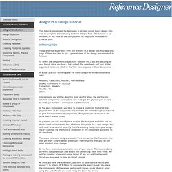
This tutorial is for Windows XP but most of the things should be easy to be extended for Linux or Unix. Those who had experience with one or more PCB design tool may skip this page. Others may like to get a general view of the design process which is follows: SPICE Simulation Community - YouSpice. Welcome to the SPICE Simulation Community Welcome to the SPICE community for electronics design and simulation.
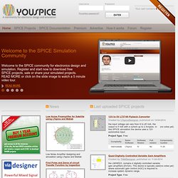
Register and start now to download free SPICE projects, sale or share your simulated projects. MOrcad speaker/crossover simulation page. SPICE. Last modified: Mai 2015 Hello all, APEC 2015 is over and I posted the PPT I presented Monday morning in front of a full--room audience. Thank you all for coming and attending my presentation, hope you liked the content! I have already ideas for next year's seminar : ) As usual, you will find the PPT in the download area. Switch-Mode Power Supplies: SPICE Simulations and Practical Designs, second edition is now completed and the book has been sent to the printer. CMOS Circuit Design, Layout, and Simulation. CMOS Circuit Design, Layout, and Simulation, Third Edition General Book Information (中文译) Published by Wiley-IEEE Press, ISBN 978-0-470-88132-3, 3rd Edition, 2010.
The book’s author is R. Jacob Baker. Buy at Amazon.ca, Amazon.cn, Amazon.fr, Amazon.de, Amazon.it, Amazon.co.jp, Amazon.co.uk, Amazon.com, or many other websites around the world. Subcircuits Page. Paul Tobin main page. Paul Tobin's web site Welcome to my web site.Here you will find PDF notes on signals and systems, active filters, transmission lines, digital signal processing, communication theory, past examination papers and solutions,and demonstrations.
The content (index)for my five PSpice textbooks can be downloaded.The design files for each book may be downloaded by selecting the PSpice page: PSpice page Select the underlined number in red below to access each course page. Conference papers Select Papers in order to download a conference paper Papers. eCircuit Center. SPICE - a brief overview. Electronics Demonstrations. SPICE Circuit Components. NPN-Bipolar Junction Transistor. Assumptions This model is a model of a bipolar NPN junction transistor according to Gummel and Poon similarly the SPICE3 BJT model of Type NPN. Interface External Parameters Input Values Results Description This model of a bipolar NPN junction transistor according to Gummel and Poon consists of the call of the model "BJT_REV" with the additional parameter Type=1.
Data Validation. NPN-BJT. Assumptions This is a dynamic Gummel and Poon model of the bipolar transistor. Interface External Parameters. BJT Spice SImulation. Spice Circuit Simulation. PSpice Tutorials. PSPICE Examples for EE-253. PSpice Examples for EE-253 Hadi Saadat PSpice allows the user to model semiconductor devices such as diodes, bipolar junction transistors (BJT), field effect transistors, and integrated circuits such as operational amplifiers. We discuss here only very simple models for the diode and BJT. Please refer to a PSpice manual for full details on these and other semiconductor devices and circuits. The resistor, capacitor, and inductor are each adequately described with a single parameter.
Diodes T he diode is a two terminal device that essentially allows current conduction in only one direction. The thermal voltage, V T , is approximately 26 mV at room temperature, so we usually only need to specify the saturation current, I S (PSpice default is I S = 10 -15 A). Download PSPICE Schematic Files for EE-253.