
The OSI Model's Seven Layers Defined and Functions Explained. The Open Systems Interconnect (OSI) model has seven layers.

This article describes and explains them, beginning with the 'lowest' in the hierarchy (the physical) and proceeding to the 'highest' (the application). The layers are stacked this way: Application Presentation Session Transport Network Data Link Physical The physical layer, the lowest layer of the OSI model, is concerned with the transmission and reception of the unstructured raw bit stream over a physical medium. It describes the electrical/optical, mechanical, and functional interfaces to the physical medium, and carries the signals for all of the higher layers. It provides: Data encoding: modifies the simple digital signal pattern (1s and 0s) used by the PC to better accommodate the characteristics of the physical medium, and to aid in bit and frame synchronization. Communications Subnet The transport layer ensures that messages are delivered error-free, in sequence, and with no losses or duplications.
End-to-end layers. Bipolar 8-Zero Substitution (B8ZS) B8ZS works in a similar way to AMI by changing poles for each binary 1.

However, there is a problem with synchronisation being lost when there is a stream of binary 0s being sent. B8ZS attempts to tackle this problem by making artificial signal changes. These signals are known as violations and occur when eight consecutive 0s occur in the bit stream. The violation signal that takes place is based on the polarity of the last binary 1 before the 8 0s and will match this polarity. Therefore, the receiving end looking for an alternate polarity to the binary 1 will discover the same polarity and will thus determine that there have been a string of 8 0s. B8ZS is a common method used in the US to avoid the synchronisation problem of long strings of binary 0s. Click on this link to review the wikipedia resource on B8ZS. Next: High Density Bipolar 3 (HDB3) Modified AMI code. Modified AMI codes are Alternate Mark Inversion (AMI) line codes in which bipolar violations may be deliberately inserted to maintain system synchronization.

There are several types of modified AMI codes, used in various T-carrier and E-carrier systems. Overview[edit] The exact pattern of bipolar violations that is transmitted in any given case depends on the line rate (i.e., the level of the line code in the T-carrier hierarchy) and the polarity of the last valid mark in the user data prior to the unacceptably long string of zeros. It would not be useful to have a violation immediately following a mark, as that would not produce a transition. For this reason, all modified AMI codes include a space (0 bit) before each violation mark. In the descriptions below, "B" denotes a balancing mark with the opposite polarity to that of the preceding mark, while "V" denotes a bipolar violation mark, which has the same polarity as the preceding mark.
Zero code suppression[edit] Examples[edit] Digital Forensics - SecurityTube Tools. OSI model. Model with 7 layers to describe communications systems The Open Systems Interconnection model (OSI model) is a conceptual model that characterizes and standardizes the communication functions of a telecommunication or computing system without regard to its underlying internal structure and technology.
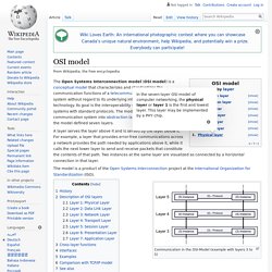
Its goal is the interoperability of diverse communication systems with standard protocols. The model partitions a communication system into abstraction layers. The original version of the model defined seven layers. A layer serves the layer above it and is served by the layer below it. The model is a product of the Open Systems Interconnection project at the International Organization for Standardization (ISO). Communication in the OSI-Model (example with layers 3 to 5) History[edit] In the late 1970s, the International Organization for Standardization (ISO) conducted a program to develop general standards and methods of networking. Description of OSI layers[edit] Layer 1: Physical Layer[edit]