
Fabriquer une passerelle domotique RFLink/RFXCom 433MHz pour 10,50€ (test avec Domoticz) RFLink est un projet Open Source qui permet de réaliser une passerelle (gateway) entre un logiciel domotique et des modules domotiques qui communiquent par ondes radio.
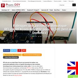
C’est une alternative très économique à la gateway commerciale RFXCom très connue. RFLink est capable de gérer les fréquences 315, 433, 868, 915MHz et depuis peu le 2,4GHz en utilisant des modules nRF24L01+. le projet RFLink est développé par Stuntteam. Vous pouvez soutenir le projet (qui permet d’acheter les nouveaux équipements domotiques) en faisant un don sur le blog du projet. RFXCom est le nom commercial d’une passerelle radio très connue et employée en domotique. La quasi totalité des logiciels domotiques prennent en charge cette passerelle mais son plus gros inconvénient reste son prix. Attention. L’équipe de Nodo travaille depuis plusieurs années maintenant sur ce projet et ajoute constamment de nouveaux matériels pris en charge par la gateway. Coût de fabrication La câblage est très simple. ArduinoCheatSheet - The Mechatronics Guy.
I really love cheat sheets.

In a lot of cases they can take the place of an entire manual. So I was surprised, given its popularity that I couldn't find a single-page reference for the arduino online. I tried to make a sheet that captured all the things I hit the reference for while programming. What data type does the millis() function return? How long till that overflows again? How to Design a PCB Layout - Circuit Basics.
Breadboards are great for prototyping circuits, but they aren’t so good for actually using the thing you’re building.
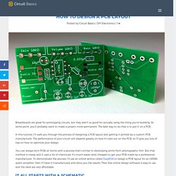
At some point, you’ll probably want to make a project more permanent. The best way to do that is to put it on a PCB. Programmez un écran LCD - Perfectionnez-vous dans la programmation Arduino. EngineerGeek – Your source for arduino tutorials and more! The $2 32-Bit Arduino (with Debugging) I have a bit of a love/hate relationship with the Arduino.
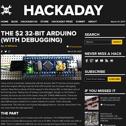
But if I had two serious gripes about the original offering it was the 8-bit CPU and the lack of proper debugging support. Now there’s plenty of 32-bit support in the Arduino IDE, so that takes care of the first big issue. Taking care of having a real debugger, though, is a bit trickier. I recently set out to use one of the cheap “blue pill” STM32 ARM boards. These are available for just a few bucks from the usual Chinese sources. The Part For a few bucks, you can’t complain about the hardware. You can find a lot more information on this wiki. From my point of view, though, I don’t want to try to debugging over the serial port and if I have the ST-Link port already set up, I don’t care about a bootloader. The “blue pill” designation is just a common nickname referring to the Matrix, not the pharmaceuticals you see on TV ads. The Plan Step 2 isn’t strictly necessary, but it will make step 5 easier.
Coding Debugging at Last. Blue Pill - STM32duino wiki. Hardware installation The USB standard require a 1.5k pullup resistor on D+, but this board is known to have a wrong value (R10 on the board).
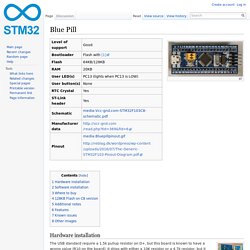
It ships with either a 10K resistor or a 4.7k resistor, but it should be replaced with a 1.5k resistor, or put an appropriate resistor value (e.g 1.8k) in between PA12 and 3.3V. It is also true that some PCs are tolerant of incorrect value so, before you change the resistance, you can try if it works in your case. Software installation Bootloader needs to be flashed using USB to Serial or ST-Link (SWD) See Flashing the bootloader Follow the normal Installation guide Note that after first flashing the bootloader you may have to place the board into "perpetual bootloader" mode before you can upload a sketch; place resistor between pin PC14 and 3.3V, then reset the board.
Where to buy Ebay or AliExpress etc 128KB Flash on C8 version. Arduino Workshop for Beginners - Tutorial Australia. Adafruit Learning System. Hackmypi. By MWAGNER Posted on March 20, 2017 at 8:00 PM Raspberry Pi Security System Part 1: The camera.
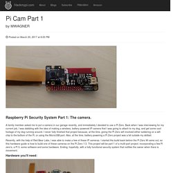
A family member asked me to put a camera in our garage recently, and immediately I decided to use a Pi Zero. Back when I was interviewing for my current job, I was dabbling with the idea of making a wireless, battery powered IP camera that I was going to attach to my dog, and get some cool footage of my dog running around. I never fully finished that project because, at the time, giving the Pi Zero wifi involved either soldering on a wifi chip to the bottom of the Pi, or using the MicroUSB port. Recently, with the help of Red Bear Labs, I was able to make a few of these IP cameras. Hardware you'll need: A Raspberry Pi Zero 1.3 Red Bear IoT pHAT Pimoroni Zero LiPo 2x20 header pins Raspberry Pi camera Pi Zero Camera Cable SD card 1500maH battery Basic Soldering equipment (Solder Iron, solder, solder wick) Start out by soldering the 2x20 pins onto the Pi Zero.
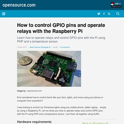
Control GPIO pins with the Raspberry Pi. Ever wondered how to control items like your fans, lights, and more using your phone or computer from anywhere?
Textbook for Electrical Engineering & Electronics.