
Getting Started Kit - kraegar. Decided to take a stab at putting together a list of parts for getting started with Arduino, using Amazon.com as a supplier.
I know you can shop around and find this cheaper, but most people like & use Amazon already. This may come out more expensive than other kits available, too, but the quantity of parts should be much, much higher. I know a lot of people say to buy stuff direct on Ebay, but shipping times are horrible, and quality is unknown. I've added a few items from Adafruit.com that I was unable to find on Amazon, or were much cheaper / better there. Obviously this can be customized further - if you don't care about motor output, don't buy the motor or Servo. Core. Parts.
Research. Arduino Lesson 10. Making Sounds. Piezo Buzzer [PS1240] ID: 160 - $1.50. Arduino Project 5: Digital audio player. So far in this series we’ve had a diverse look at how Arduino can interact with a range of real-world devices from servo motors to ultrasonic range finders TVs to humidity sensors.
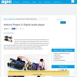
Now we’ll see if we could get the Arduino to make a few sounds. We’ll actually do a bit better than that – we’ll look at the importance of pulse width modulation (PWM) to microcontrollers by building our own digital audio player called Auduino. The two versions of our Auduino audio player. The Ethernet shield version (bottom) gives better results with more flash cards. What we’re building. Simple Arduino audio samples. This tutorial explains how to do simple playback of short (~4 second), low-bitrate (8 KHz) audio samples from Arduino using only a speaker.
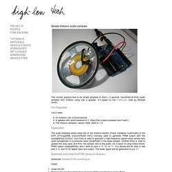
It’s based on the PCMAudio code by Michael Smith. Pre-Requisites You’ll need: An Arduino Uno or DuemilanoveA speaker with wires soldered to it. (Note that a piezo probably won’t work.)The Arduino software, version 0022, 0023 or 1.0 Explanation The audio playback works using two of the Arduino board’s timers, hardware functionality of the AVR (ATmega328) microcontroller that’s normally used to generate PWM output with the analogWrite() function. ATmega168. Get Started We'll tell you all you need to know to start evaluating and working with this product.
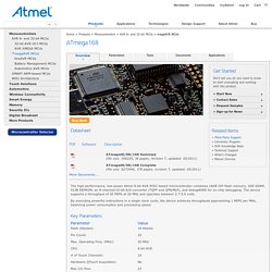
Buy Now Datasheet ATmega48/88/168 Summary(file size: 506229, 36 pages, revision T, updated: 05/2011) InterfacingWithHardware. These topics cover the hardware and software setup required to connect an Arduino device with a variety of electronic parts, chips and devices.
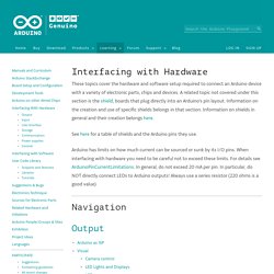
A related topic not covered under this section is the shield, boards that plug directly into an Arduino's pin layout. Information on the creation and use of specific shields belongs in that section. Information on shields in general and their creation belongs here. See here for a table of shields and the Arduino pins they use. Arduino has limits on how much current can be sourced or sunk by its I/O pins. Navigation Output Input User interface Buttons,Encoders,Keypads Unified Input InterfaceText-based user interfacemicroBox Linux Shell look and feel for Arduino Phi_prompt user interface LibraryMenuSamplePhi_prompt glcd user interface Library This is being planned. Communication General Common Pinouts Examples and information for specific output devices and peripherals: How to connect and wire up devices and code to drive them. Visual. Arduino Audio Output.
DAC stands for "digital to analog converter.
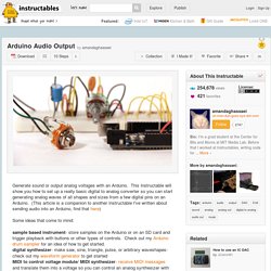
" Since the Arduino does not have analog out capabilities, we need to use a DAC to convert digital data (numbers/ints/bytes) to an analog waveform (oscillating voltage). A simple, easy to program, and cheap way to do this is to use something called an R2R resistor ladder. Essentially, it takes incoming digital bits (0V and 5V from Arduino), weights them, and sums them to produce a voltage between 0 and 5 volts (see the schematic in fig 2, taken from the Wikipedia resistor ladder page).
You can think of a resistor ladder as a multi-leveled voltage divider. The resistor ladder I'll be demonstrating in this tutorial is an 8-bit DAC, this means it can produce 256 (2^8) different voltage levels between 0 and 5v. I like using these resistor ladder DACs because I always have the materials around, they're cheap, and I think they're kind of fun, but they will not give you the highest quality audio. Recorder [811020001] Grove - Recorder is based on ISD1820P, which can record 8~20 sec by set resistor and cycle play.
![Recorder [811020001]](http://cdn.pearltrees.com/s/pic/th/recorder-811020001-seeedstudio-88108512)
It can offers true single-chip voice recording, no-volatile storage. Grove - Recorder is 100K and the total 10s for Recorder. This module is very easy to control, which can direct control by push button on board or by microcontroller. Features. Loudness Sensor [SEN02281P] The Grove - Loudness Sensor is designed to detect the loudness of environmental sound.
![Loudness Sensor [SEN02281P]](http://cdn.pearltrees.com/s/pic/th/loudness-sen02281p-seeedstudio-88108502)
Based on amplifier LM2904 and a built-in microphone, it amplifies and filters the high frequency signal that received from the microphone, and outputs a positive envelop. This will make for Arduino’s signal acquisition. Grove - Loudness Sensor. [中文] Introduction The Grove - Loudness Sensor is designed to detect the loudness of environmental sound.
Based on amplifier LM2904 and a built-in microphone, it amplifies and filters the high frequency signal that received from the microphone, and outputs a positive envelop. This will make for Arduino’s signal acquisition. The output value depends on the level of sound input. Previous Version: v0.9bModel:SEN02281P Specifications Voltage :3.5~10 VDC Working Frequency :50~2000 Hz Sensitivity : -48~66 dB Signal-to-noise Ratio : >58 dB Output Signal range : Analog Signal (0-1023) Demonstration With Arduino This module uses the chip LM2904 to amplify the electronic signal produced by the mini microphone. As the picture on the below indicates, the Loudness sensor is connected to analog port A0 of the Grove - Basic Shield Connect Arduino/Seeeduino to PC by using a USB cable.
Upload the code.Then open the serial monitor to observe the output results.