
UML basics: The component diagram. This is the next installment in a series of articles about the essential diagrams used within the Unified Modeling Language, or UML.
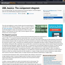
In my previous article on the UML's class diagram, (The Rational Edge, September 2004), I described how the class diagram's notation set is the basis for all UML 2's structure diagrams. Continuing down the track of UML 2 structure diagrams, this article introduces the component diagram. The diagram's purpose The component diagram's main purpose is to show the structural relationships between the components of a system. In UML 1.1, a component represented implementation items, such as files and executables. In component-based development (CBD), component diagrams offer architects a natural format to begin modeling a solution.
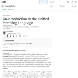
In addition, component diagrams are useful communication tools for various groups. Back to top. UML basics: An introduction to the Unified Modeling Language. UML basics Getting started with visual modeling of your software Donald BellPublished on June 15, 2003 Way back in the late twentieth century —
UML 2 Activity Diagramming Guidelines. Guidelines: 1.
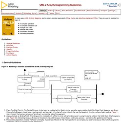
General Guidelines Figure 1. Modeling a business process with a UML Activity Diagram. Place The Start Point In The Top-Left Corner. 2. An activity, also known as an activity state, on a UML Activity diagram typically represents the invocation of an operation, a step in a business process, or an entire business process. Question "Black Hole" Activities. Unified Modeling Language. The Unified Modeling Language (UML) is a general-purpose modeling language in the field of software engineering, which is designed to provide a standard way to visualize the design of a system.[1] It was created and developed by Grady Booch, Ivar Jacobson and James Rumbaugh at Rational Software during 1994–95 with further development led by them through 1996.[1] In 1997 it was adopted as a standard by the Object Management Group (OMG), and has been managed by this organization ever since.
Papyrus UML - Welcome to Papyrus UML web site. Class and sequence diagrams work together to allow precise modeling. UML is used as a representation of the Java programming language.
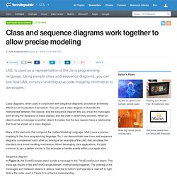
Using sample class and sequence diagrams, you can see how UML conveys unambiguous code-mapping information to developers. Class diagrams, when used in conjunction with sequence diagrams, provide an extremely effective communication mechanism. You can use a class diagram to illustrate the relationships between the classes, and the sequence diagram lets you show the messages sent among the instances of these classes and the order in which they are sent. When an object sends a message to another object, it implies that the two classes have a relationship that must be shown on a class diagram. UML graphical notation overview, UML diagram examples, tutorials and reference.
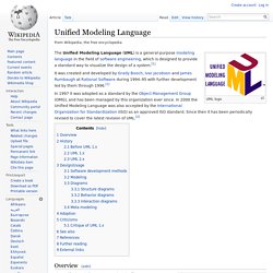
Behavior Diagrams. Agile Modeling (AM) Home Page: Effective Practices for Modeling and Documentation. UML 2.2 Tutorial: Activity Diagrams and Subactivities. Introduction to UML 2 Class Diagrams. UML 2 class diagrams are the mainstay of object-oriented analysis and design.
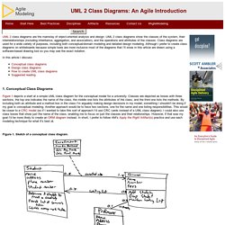
UML 2 class diagrams show the classes of the system, their interrelationships (including inheritance, aggregation, and association), and the operations and attributes of the classes. Class diagrams are used for a wide variety of purposes, including both conceptual/domain modeling and detailed design modeling. Although I prefer to create class diagrams on whiteboards because simple tools are more inclusive most of the diagrams that I'll show in this article are drawn using a software-based drawing tool so you may see the exact notation. In this article I discuss: 1. Figure 1 depicts a start at a simple UML class diagram for the conceptual model for a university. Figure 1. Enrollment is an associative class, also called a link class, which is used to model associations that have methods and attributes. Figure 2 depicts a reworked version of Figure 1, the associative class has been resolved.
UML class diagram cheat sheet. During my MSc studies I had to design and develop a game for my dissertation.
My MSc dissertation topic was “Developing a Game to aid Object-oriented programming learning”. The game was designed to utilize UML class diagrams in order to “teach” the basic object oriented concept. The main idea behind it was that the players will take the role of an employee in an international company and they will have to travel around the world to solve particular problems. Agile Modeling (AM) Home Page: Effective Practices for Modeling and Documentation. UML Overview.
Introduction Modeling is an activity that has been carried out over the years in software development.
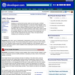
When writing applications by using the simplest languages to the most powerful and complex languages, you still need to model. Modeling can be as straightforward as drawing a flowchart listing the steps carried out by an application. Why do we use modeling? Defining a model makes it easier to break up a complex application or a huge system into simple, discrete pieces that can be individually studied. ReadabilityReusability Readability brings clarity—ease of understanding. Reusability is the byproduct of making a system readable. Even though there are many techniques and tools for modeling, in this article series, we will be concerning ourselves with modeling object-oriented systems and applications using the Unified Modeling Language.