
Arduino Workshop. Page 6: Two suppliers to add to the list are: Altronics ( Jaycar ( Page 13: The first sentence on the page should read, "Copy the folder named arduino-1.0.5-windows (or something similar)...

" Page 27: The first sentence on the page should read, "At the bottom right of the message area, you should see the name of your Arduino board type as well as its connected USB port- Arduino Uno on COM4 in this case. " Page 75: In Figure 4-26, there should be a ground connection on the line that connects R7 with R8. Optiboot - An optimised bootloader for Arduino platforms. Fun with 8×8 LED Matrix. I’ve finally got around to wiring up my 8×8 LED Matrix and now it’s time for some fun with it.
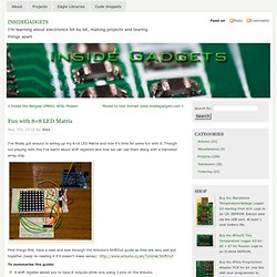
Though out playing with this I’ve learnt about shift registers and how we can use them along with a transistor array chip. First things first, have a read and look through the Arduino’s ShiftOut guide as they are very well put together (keep re-reading it if it doesn’t make sense): To summarise the guide: A shift register allows you to have 8 outputs while only using 3 pins on the ArduinoYou send a byte to the shift register which has 8 bits (e.g. 10010000)You can combine shift registers so instead of having only 8 outputs you can have 16 when using 2, 24 when using 3, and so onWhen combining shift registers, instead of sending out the 8 bits to the first register and 8 to the second register it’s actually reversed, so the first 8 bits you send are actually for the second register and the next 8 bits go to the first register This is an example to use with only 1 shift register.
Parts used Software. LED Matrix Link: Prototype. Update: I have listed the LED Matrix Link on Tindie as a fundraiser to get this started.

You can support it here: This prototype stems from another project\product to be that I haven't posted about except for this sneak peak: Project Sneak Peak. I noticed that most LED Matrix drivers on the market use shift registers to give a microcontroller the ability to control more LEDs than would be possible. Last year I came across the MAX7219 from Maxim Integrated. This cool little IC does all the work for you to drive a LED Matrix or LED Segment display. Since I have been playing with this IC and getting to know it I decided to make a carrier board that fits on the back of a 3mm (each LED size) LED Matrix. One of my uses for this is I want to setup 8 of them to display messages during the reception for my upcoming May wedding. uDuino.com. Arduino - Céupédia. This page is about running the Céu programming language under the Arduino platform. 1 Installation You can either download a virtual machine preloaded with Céu, or install it manually from the git repository: 2 Examples The distribution comes with some samples ready for playing with Céu.
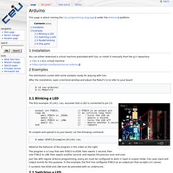
After the installation, open a terminal window and adjust the Makefile to refer to your board: $ cd ceu-arduino/ $ vi Makefile 2.1 Blinking a LED The first example, blink1.ceu, assumes that a LED is connected to pin 13: output int PIN13; // PIN13 is an output pin loop do // an infinite loop that: emit PIN13 => _HIGH; // - turns the LED on await 1s; // - awaits 1 second emit PIN13 => _LOW; // - turns the LED off await 1s; // - awaits another 1 second end // - repeats. Lab 12: Basics of LED dot matrix display. We covered how to interface seven segment LED displays to a PIC microcontroller in two sections: Lab 6 and Lab 11.
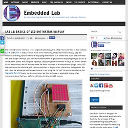
Today, we will move on to interfacing an LED dot matrix display. LED dot matrices are very popular means of displaying information as it allows both static and animated text and images. Perhaps, you have encountered them at gas stations displaying the gas prices, or in the public places and alongside highways, displaying advertisements on large dot matrix panels. In this experiment, we will discuss about the basic structure of a monochrome (single color) LED dot matrix and its interface with a microcontroller to display static characters and symbols. We will cover the animation stuff in next tutorial.
Interfacing a LED dot matrix display with a PIC microcontroller Theory of LED dot matrix display In a dot matrix display, multiple LEDs are wired together in rows and columns. Structure of a 8x8 LED dot matrix The LED matrix used in this experiment is of size 5×7. Circuit Setup.