
Untitled. Image File (.rst) -- File Structure Use Image files are the data files most commonly used in IDRISI.
They store the raster data layers used in analyses. File Contents Image files contain the attribute value of each pixel in the image. Creation Image files are created by most IDRISI modules. RayTrace software, release 3.3. {*style:<b>Author: Sam Buss Univ. of California, San Diego </b>*} [ View this page in Romanian , translation by Alexandra Seremina, courtesy of azoft .
Or in German , translation by Maksim Ivancov.] This software package accompanies my book (Cambridge University Press, 2003). r2d manual. Ray Tracing News, Volume 3, Number 4. Ray Tracing News "Light Makes Right" October 1, 1990 Volume 3, Number 4 Compiled by erich@acm.org . Opinions expressed are mine. All contents are copyright (c) 1990, all rights reserved by the individual authors Archive locations: anonymous FTP at wuarchive.wustl.edu:/graphics/graphics/RTNews, and many others.
You may also want to check out the Ray Tracing News issue guide and the ray tracing FAQ. ========Net News Cullings======== Raster Mapping Formats - Raster Maps - Raster Scanned Maps. ADRG Files Description: ADRG is a raster format typically used by military and other government organizations.
To load ADRG files, simply load the TRANSH01.THF file from the ADRG file heirarchy or load the ADRG data directly from a .zip file. Global Mapper v6.02 and above can load files in this format. ARCS (British Admiralty) Marine Charts The ARCS marine chart format is used by the British Admiralty UKHO and others for marine charts. Web Pages and FTP Sites: TRANSVERSE MERCATOR FORMULAE. Great Circle Mapper. Gridspec: A standard for the description of grids used in Earth System models. PRINTSCRIPT; print $script_style; include "/var/www/html/core/partc"; $linkpage = <<< PRINTLINK gfdl homepage > people > v. balaji's homepage > this page PRINTLINK; print $linkpage; // GFDL header include "/var/www/html/core/partd"; $titlepage = <<< TITLEPAGE Gridspec: A standard for the description of grids used in Earth System models TITLEPAGE; print $titlepage; // GFDL header include_once( '/var/lib/php/counter.inc' ); error_reporting(E_ERROR); require_once('..
/magpierss/rss_fetch.inc'); require_once('.. /magpierss/rss_utils.inc'); include "/var/www/html/core/parte"; $pagecontent = <<< ENDCONTENT 2. Grid terminology for Earth System science We begin by developing a terminology for describing the types of grids used in Earth System science models and datasets. Coordinate conversions made easy. Untitled. Los Alamos Climate Ocean and Sea Ice Modeling: Software: SCRIP. Mission: The purpose of the COSIM project is to develop, test and apply ocean and ice models in support of DOE Climate Change Research and the Long Term Measure of delivering improved climate data and models needed to determine acceptable levels of greenhouse gases in the atmosphere.
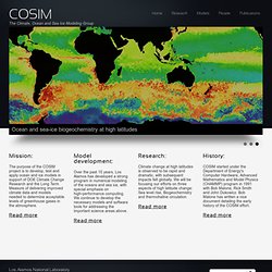
Read more Model development: Over the past 15 years, Los Alamos has developed a strong program in numerical modeling of the oceans and sea ice, with special emphasis on high-performance computing. We continue to develop the necessary models and software tools for addressing the important science areas above. Read more. Map Projections Poster. Transverse Mercator. Projection Parameters PROJ.4 Organization +proj=tmerc +lat_0=Latitude of natural origin +lon_0=Longitude of natural origin +k=Scale factor at natural origin +x_0=False Easting +y_0=False Northing EPSG Notes The Transverse Mercator projection in its various forms is the most widely used projected coordinate system for world topographical and offshore mapping.
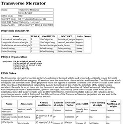
All versions have the same basic characteristics and formulas. The most familiar and commonly used Transverse Mercator is the Universal Transverse Mercator (UTM) whose natural origin lies on the equator. Triangle: .node files. Weiler-atherton polygon clipping - Google Search. Weiler-Atherton Clipping Applet. Background The Weiler-Atherton clipping algorithm is a general purpose 2D clipping algorithm.
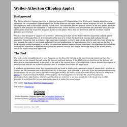
While most clipping algorithms are optimized for a rectangular clipping region, the Wieler-Atherton algorithm can use simple polygons for both the subject of the clipping as well as the actual clipping region itself. The algorithm has two general phases. In the first phase, all of the edges of both polygons are examined to find intersections.
These intersections are inserted into point lists along with all of the points from the respective polygons. Polygon Area. Quadrilateral Intersection Area. Spherical Polygon. Spherical polygon centroid. Polygon Class Reference. Geographische in Gauß-Krüger-Koordinaten umrechnen - Delphi-Treff. Introduction to Geometric Computing. Mercator projection: why aren't parallels equidistant? [Archive] As pointed out earlier, on a globe one degree of latitude is the same distance everywhere. Gaussian grid. A Gaussian grid is used in the earth sciences as a gridded horizontal coordinate system for scientific modeling on a sphere (i.e., the approximate shape of the Earth).
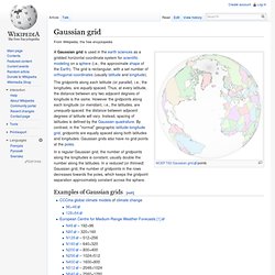
The grid is rectangular, with a set number of orthogonal coordinates (usually latitude and longitude). The gridpoints along each latitude (or parallel), i.e., the longitudes, are equally spaced. Thus, at every latitude, the distance between any two adjacent degrees of longitude is the same. However the gridpoints along each longitude (or meridian), i.e., the latitudes, are unequally spaced: the distance between adjacent degrees of latitude will vary. Haversine formula. The haversine formula is an equation important in navigation, giving great-circle distances between two points on a sphere from their longitudes and latitudes.
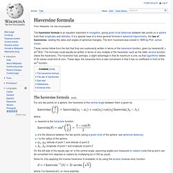
It is a special case of a more general formula in spherical trigonometry, the law of haversines, relating the sides and angles of spherical triangles. The term haversine was coined in 1835 by Prof. James Inman. Map projection. More generally, the surfaces of planetary bodies can be mapped even if they are too irregular to be modeled well with a sphere or ellipsoid; see below.
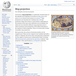
Even more generally, projections are the subject of several pure mathematical fields, including differential geometry and projective geometry. However "map projection" refers specifically to a cartographic projection. Background[edit] Polygon triangulation. In computational geometry, polygon triangulation is the decomposition of a polygonal area (simple polygon) P into a set of triangles,[1] i.e., finding the set of triangles with pairwise non-intersecting interiors whose union is P. Triangulations may be viewed as special cases of planar straight-line graphs. When there are no holes or added points, triangulations form maximal outerplanar graphs. Polygon triangulation without extra vertices[edit] Over time a number of algorithms have been proposed to triangulate a polygon. Special cases[edit]
Space-filling curve. Three iterations of the Peano curve construction, whose limit is a space-filling curve. Definition[edit] Intersecting convex Polygons. Briefly... Let P and Q be two convex polygons whose intersection is a convex polygon.The algorithm for finding this convex intersection polygon can be described by these three steps: Construct the convex hull of the union of P and Q; For each pocket lid of the convex hull, find the intersection of P and Q that lies in the pocket; Merge together the polygonal chains between the intersection points found in 2.What's a pocket lid? Weiler-Atherton Algorithm. Sweep Line Algorithm for Segment Intersection. Bentley–Ottmann algorithm. Algorithm - area of intersection of two triangles, or a set of halfplanes, or area of a convex point set. Point-in-polygon: Jordan Curve Theorem - Sidvind. Does this algorithm have a name? Oct 20, 2010 at 10:47pm. EGSnrc C++ class library: Geometry module. This module contains classes that model various geometry types.
Computational Geometry, C++ and Wykobi. Download source - 108 Kb. Introduction. Calculate distance and bearing between two Latitude/Longitude points using Haversine formula in JavaScript.