
Soft Clipping. Copyright © 2006 - Rod Elliott (ESP) Page Created 15 April 2006 Articles Index Main Index Contents 1 - Introduction There seems to be something really nice about the idea of soft clipping.

Figure 1 - Comparison of Transistor (Red) and Valve (Green) Clipping The 'soft' characteristic (Green) shown in Figure 1 has few high order harmonics. Figure 2 - Spectrum of Transistor (Red) and Valve (Green) Clipping Distortion Note that the ragged looking transistor spectrum at low levels may appear to be 'bad', but all such signal levels are at about 1uV, so are around 120dB below the amplitude of the fundamental. 2 - Soft Clip Circuit Apart from the obvious solution of using a valve output stage (hardly a simple modification to an existing circuit), the easiest way to make a circuit that clips 'softly' is to use diodes. Figure 3 - Basic Soft Clip Circuit Figure 3 shows the basic schematic of a soft clip circuit.
The value of R1 is surprisingly very important. Table 2 - Measured vs. 3 - Amp Power Reduction. Guitar Buffer Circuits. Transistor Buffers Here is a very simple and effective buffer from Jack Orman.

Using a low-gain JFET transistor, this design is as simple as it gets--input cap, bias resistor, and output cap. Next up is the single-transistor buffer as found in the Ibanez Tube Screamer--a bit more complex, but your ears will be the guide as to whether or not it sounds better. Opamp Buffers Opamps make great buffers. Here is the opamp-based buffer section from a famous boutique overdrive that rhymes with "Plon Fentar". Let's Build One! You can build a simple buffer using any kind of stripboard/perfboard.
Click on the Image for a Larger Version! Recommended Reading. LTH logging interface with the PICAXE-08M. Hello and welcome!

This is an informal description of a project I got into, to build an interface to collect measurements of light intensity, temperature and relative humidity using the PICAXE-08M microcontroller (µC) and a computer's serial port. I needed to measure these parameters pronto for my thesis project and, in haste, I hacked this thing together, or rather glued it together (quite literally!). Please e-mail me if you have questions or comments. cirelli $AT! Ualberta %DOT& ca Contents Motivation The astute reader will surely ask why in the world I didn't use something more sensible, something with higher resolution and/or more legs.
Resolution is not a huge deal actually; the 08M comes with a 10-bit ADC, and averaging over a changing variable will give you an improved resolution. Disclaimer & Licenses The fine print: I only graze the surface of electronics, even as a hobby. There, with the formalities out of the way, let's proceed... Brief intro The concept here is simple: Presto! Why 127 max USB devices? USB packets look like this: Token: Packet ID: 8 bits Address: 7 bits Endpoint: 4 bits CRC: 5 bits Start of frame: Packet ID: 8 bits Frame Number: 11 bits CRC: 5 bits.

HVW Technologies: Microcontrollers, Embedded Software, Development Tools and Robotics. Build an FM Antenna - Powered by Google Docs. Guitar Pedals: R-C Filter Calculator. Resistor color code calculator - 3, 4 and 5 band resistors. The calculator above will display the value, the tolerance and performs a simple check to verify if the calculated resistance matches one of the EIA standard values.
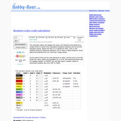
Select the first 3 or 4 bands for 20%, 10% or 5% resistors and all 5 bands for precision (2% or less), 5-band resistors. Hover above the tolerance for min. and max. range values. If you want to find out the color bands for a value, use the tool on the left. Enter the value, select the multiplier (Ω, K or M), the desired precision and hit 'Display resistor' or ENTER. You can also type in resistor values in shorthand notation like 1k5, 4M7 or 100R. Standard EIA Decade Resistor Values: E6 series: (20% tolerance)10, 15, 22, 33, 47, 68 E12 series: (10% tolerance) 10, 12, 15, 18, 22, 27, 33, 39, 47, 56, 68, 82 E24 series: (5% tolerance) 10, 11, 12, 13, 15, 16, 18, 20, 22, 24, 27, 30, 33, 36, 39, 43, 47, 51, 56, 62, 68, 75, 82, 91 FAQs I have a 6-band resistor.
Enter the first five colors. The resistor has only 3 bands 1.) 2.) 3.) Notes.