
Andy Bardagjy » EagleCAD and Advanced Circuits. Ouch. UPDATE I have posted an automated tools for gerber export here UPDATE So congratulations! You just routed 3000 nets and placed 250 components! You are probably going a little crazy, seeing things that could be placed more efficiently and thinking about how you would route them. Well you’re not out of the woods yet! These notes are relative to EAGLE CAD and Advanced Circuits (including 33each/barebones). I’ll talk about gerbmerge in another post. Passing DRC This should be no big deal because you have been regularly checking DRC (Design Rule Check) in Eagle right? Of course, when routing a board, do not use the minimum trace widths and spacings unless you have to!
Generating Gerbers Advanced PCB Layers First, in the command line, run drillcfg to generate a .drl file. Next, create excellon drill files by clicking file -> cam or press the cam button. To generate the drill files, from within the CAM dialog, select file -> open -> job. Use gerbv to preview those files. Electronics Forum -> Eagle Footprint. EAGLE Parts. ArduinoBoardMega. Overview The Arduino Mega is a microcontroller board based on the ATmega1280 (datasheet).
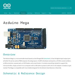
It has 54 digital input/output pins (of which 14 can be used as PWM outputs), 16 analog inputs, 4 UARTs (hardware serial ports), a 16 MHz crystal oscillator, a USB connection, a power jack, an ICSP header, and a reset button. It contains everything needed to support the microcontroller; simply connect it to a computer with a USB cable or power it with a AC-to-DC adapter or battery to get started. The Mega is compatible with most shields designed for the Arduino Duemilanove or Diecimila. Schematic & Reference Design EAGLE files: arduino-mega-reference-design.zip Schematic: arduino-mega-schematic.pdf Summary Power The Arduino Mega can be powered via the USB connection or with an external power supply. External (non-USB) power can come either from an AC-to-DC adapter (wall-wart) or battery. The board can operate on an external supply of 6 to 20 volts. The power pins are as follows: VIN.
Memory AREF. I2C Bus Technical Overview and FAQ - Embedded Systems Academy. Based on the I2C FAQ by Vince Himpe In the early 1980's, NXP Semiconductors developed a simple bi-directional 2-wire bus for efficient inter-IC control. This bus is called the Inter-IC or I2C-bus. At present, NXP's IC range includes more than 150 CMOS and bipolar I2C-bus compatible types for performing communication functions between intelligent control devices (e.g. microcontrollers), general-purpose circuits (e.g. LCD drivers, remote I/O ports, memories) and application-oriented circuits (e.g. digital tuning and signal processing circuits for radio and video systems). All I2C-bus compatible devices incorporate an on-chip interface which allows them to communicate directly with each other via the I2C-bus. General Introduction I2C Bus Events Frequently Asked Questions Miscellaneous Information.