
Measuring Temperature From PT100 Using Arduino - All. The full circuit is shown above and it was made in Autodesk's new Circuits.io which lets you created circuits on breadboard, edit circuit diagram(shown in picture 2) and PCB diagrams and the best part, lets you simulate the circuit from the breadboard and can even program an Arduino and connect it in the breadboard mode, further down the page is the simulation and you can play around with two pots.
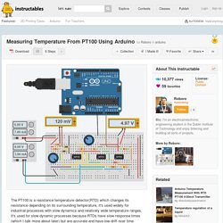
If you want to duplicate the circuit and put in your own values, you can find the circuit here. The first pot is 70ohms and in series with an 80ohm resistor which simulates the PT100 with a range of 80-150ohms, the second pot is the gain of the instrumentation amp. Sadly I used a library I downloaded for my code, so the Arduino isn't included in the circuit below but the there's only two extra wires you need to connect. If you are more comfortable with LTspice, I included an asc file with the circuit. Connect A0 pin to the output of the Differential amp Blog: Roboroblog. Help Center - Powerpole Assembly Instructions. Assemble the red and black plastic housings together correctly on the first try, they fit snugly and can be difficult to get apart.
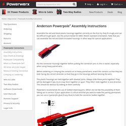
See the picture below for ARES /RACES standard orientation. Note that you can assemble the red and black insulated housings in other ways for special applications. Put the connector housings together before putting the connector pins in, this is easier, especially when using heavy paired wire.
IMU - 9 DOF. Blue tooth. Home station. Coding tips. Batteries and charging. Schurs robotics. Typically, the first sensors a robot builder installs on their new robotic creation is a frontal bumper.

As to what they plan to do with these sensors is generally vague, there is little detailed information describing the behaviors to implement in the programming. Most books seem to skim over the subject – indeed, other than "Turn right for left impact" and "Turn left for right impact", most publications move on to other more enticing subjects such as sonar, or mapping. So here we wish to fill in that critical gap in information and discuss in more detail the issues that lie beyond simple "Bumper logic". Schmitt Trigger Applications. Willkommen auf ArduMower.de. Details Details Kategorie: Blog Veröffentlicht am Sonntag, 18.
August 2013 15:22. Electronics UDO 5. ELM4701 - ELM Project I. Www.ic-meter.com/dk/wp-content/uploads/2013/06/PSP103.pdf. Www.ic-meter.com/dk/wp-content/uploads/2013/06/Sensirion_Humidity_SHT21_Datasheet_V3.pdf. Www.ti.com/lit/an/slyt442/slyt442.pdf. Lubosweb.php5.sk/konstrukcie/06_termostat_pt100/Application Note_11.pdf. How to Build a Robot Tutorials - Society of Robots.
Sensors. IR. Motors and wheels. BWF - Buried Wire Fence. Robot Projects. Robot Projects Sam Wane Tele-operated Gripper Alex the talking head The PIG This robot was built at Staffordshire University with the help of Steve Knight (hardware). Low level driving H-Bridge The problem with H-Bridge motor drivers. Motor (a) will turn when the gate voltage is between 2-4V. …and the other way when FETS Q4 and Q6 are conducting: FETs Q4 and Q5 are switched to set the direction, the PWM signal switches either Q1 or Q6 depending on whether the DIR (direction) line is low or high. Components: R1,R5,R8,R10 12k R2, R6, R9, R11 3.3k R3, R12 33k R7, R4, R13, R14, R15 47k R16 1k Q1, Q6 MTP36N06V Q4, Q5 MTP30P06V Q3, Q10 BC212 Q2, Q7, Q8, Q9, Q11 BC108 D1,D2,D3,D4 large current diodes Note that the PCB diagram may not be to scale!
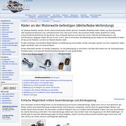
Zubehoer für autonome mobile Roboter, Sensorik, Elektronikmodule. Kleines Tutorial für Roboter-Bastler. Motor und Räder montieren und befestigen.
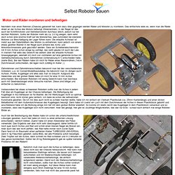
Räder an der Motorwelle befestigen (Welle/Nabe-Verbindung) Aus RN-Wissen, der freien Wissensdatenbank.
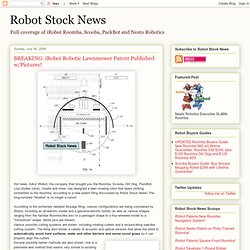
Electronics UDO 5. Robotics - What can I use to detect pinpoint location (inches) outdoors? - Electrical Engineering. Pnavhe11.irccyn.ec-nantes.fr/material/session3/Codol_paper.pdf. Robomow.ion.org/wp-content/uploads/2011/12/2011_WSU2_Moogie.pdf. Robot MarketPlace - 674 NPC Geared Motors. BREAKING: iRobot Robotic Lawnmower Patent Published w/Pictures! Hot news, folks!
Clamping Hubs. Drilling Multiple Setscrew Holes in a Vise at 120 Degree Angles. On the prior page, we drilled precise screw holes in a cylinder using a digital readout.
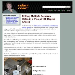
The final purpose of those holes is to firmly attach a Lego wheel. To fully convert the raw cylinder into a coupler, screw holes must now be drilled in sides of the cylinder to tighten screws against the motor shaft. Less rugged couplers use only a single screw. Professional couplers tend to use two screws at 90 degree angles. To better ensure against wheel loss, this coupler will have three screw holes spaced evenly at 120 degrees. One of the most difficult aspects of drilling setscrew holes is to make sure they will exit in the center hole where the motor shaft will reside. David Cook's Robot Room: Robotics, Circuits, and Machining. DC Motor Mounts and Wheel Couplers, Page 4. (continued from previous page) Precision DC motors can be very expensive -- particularly for larger motors.
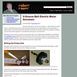
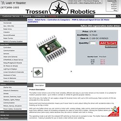
Although larger motors often have ball bearings on the output shaft, it isn’t a good idea to subject them to non-rotational loads and physical shocks if it can be avoided. One method of isolating a motor from wheel impacts is to transfer the motor power via a belt drive. SyRen 25A regenerative motor driver. Product Description The SyRen motor driver is one of the most versatile, efficient and easy to use motor drivers on the market.
How to Build a Robot Tutorial - Society of Robots. Plastics It should not be hard to convince anyone the benefit of using plastics instead of metals for so many applications. Cars, clothes, food containers, toys - these are all items that have been revolutionized by the invention of plastics. Plastic is cheaper, lighter, more corrosion proof, easier to cut and shape and drill, has a very low thermal conductivity, and a higher strength to weight ratio than metals. So why isn't your robot made of plastic already? It is probably because you do not know where you can get large cheap quantities of the stuff, nor have you actually realized the advantages of it. Arduino Robotics - John-David Warren, Josh Adams, Harald Molle. Hubert's robots page. Arduino Robot 2 - Wandering Tank. Robot Store. How It Works: Husqvarna AutoMower 305. DIY Robot Lawn Mower. GARDENA Mähroboter R40Li - Installation (Teil 6: Begrenzungs- und Leitkabel) Fully Autonomous Golf Caddy. I'm getting pretty good at Arduino programming.