
Pojpoj.se. Wire guidance sensor. Wire guidance sensor When I visited Legoland Deutchland, I wondered how vehicles circulating in Miniland were guided.
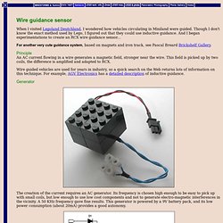
Though I don't know the exact method used by Lego, I figured out that they could use inductive guidance. And I began experimentations to create an RCX wire guidance sensor... For another very cute guidance system, based on magnets and iron track, see Pascal Breard Brickshelf Gallery. Principle An AC current flowing in a wire generates a magnetic field, stronger near the wire.
Wire guided vehicles are used for years in industry, so a quick search on the Web returns lots of information on this technique. Generator The creation of the current requires an AC generator. Circuit analysis This circuit is very simple: a NE555 timer generates a square wave which is converted to a sinusoidal wave with L1/C1 tuned circuit. You can see here a simulation of this circuit operation, obtained with Circuit Maker Student. Construction Sensor Test robot. Der NAIL SEEKER. Radar Basics - Pulse Compression. Intrapulse Modulation and Pulse Compression Pulse compression is a generic term that is used to describe a waveshaping process that is produced as a propagating waveform is modified by the electrical network properties of the transmission line.
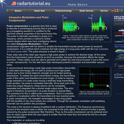
The pulse is internally modulated in phase or in frequency, which provides a method to further resolve targets which may have overlapping returns (so called Intrapulse Modulation). Pulse compression originated with the desire to amplify the transmitted impulse (peak) power by temporal compression. It is a method which combines the high energy of a long pulse width with the high resolution of a short pulse width.
The pulse structure is shown in figure 1. Pulse radar sets of the older type require a high pulse power to achieve the desired range. Figure 2: short pulse (blue) and a long pulse with intrapulsemodulation (green) The noise in the receiver is always broadband with a random distribution. This modulation or coding can be either summary devices. Barker code. Begrenzungsschleife - Induktionsschleife – RN-Wissen.de. Eine Begrenzungsschleife oder Induktionsschleife wird verwendet, um den Arbeitsbereich eines Roboters festzulegen.
Üblicherweise wird diese bei Rasenmäherrobotern eingesetzt. Die Induktionsschleife wird dabei um die zu mähende Fläche verlegt. Ein Roboter kann auch entlang einer Induktionsschleife zur Ladestation geleitet werden. Funktionsprinzip: Als Induktionsschleife wird ein Kabel (Schaltlitze, Lautsprecherkabel) verlegt. Entscheidend für die Funktion ist somit nicht das statische Magnetfeld.
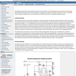
Senderschaltung: Die Ansteuerung des MOSFET T1 ist über beliebige Timer (NE555, Attiny2313) möglich. Der Widerstand R5 muss etwas Leistung verkraften können, ein 4W-Typ ist sicher ausreichend. Genauer einstellbar sind Impulsbreite und Wiederholfrequenz, wenn statt des NE555 ein Mikrocontroller verwendet wird. Empfangsschaltung: 1. Eine geeignete Detektorspule kann aus einem Relais (z.B. 12 - 24 V, Widerstand etwa 500 Ohm) ausgebaut werden. Untitled. Description: Fixed Inductors 100mH 10% 25KHz 20mA Images are for reference onlySee Product Specifications Log In to create a note about this product or see notes that you previously created on this product.

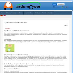
Real Time Availability Stock: 3.130 Can Dispatch Immediately Factory Lead Time: 13 Weeks Pricing (EUR) Allow shipping of Partial Reels In Stock To add to a project, please Log In. Induktionsschleife. Induktionsschleife / IR-Baken Details Details Kategorie: Instructions Veröffentlicht am Montag, 19.
August 2013 20:03 Geschrieben von AlexanderG. Rasenrobo mit Induktionsschleife, Schaltbilder, Hallsensor - Roboternetz-Forum. Begrenzungsschleife - Induktionsschleife - RN-Wissen. Wire guidance sensor. Oboe (navigation) Each Oboe station used the radio ranging to define a circle of specific radius, with the intersection of the two circles pinpointing the target.
The Mosquito flew along the circumference of the circle defined by one station, known as the "Cat", and dropped its load (either bombs, or marking flares, depending on the mission) when it reached the intersection with the circle defined by another station, known as "Mouse". There was a network of Oboe stations over southern England, and any of the stations could be operated as a Cat or a Mouse as the need demanded. Various Morse letters could also be sent, for example to notify the aircraft crew that the Mosquito was within a specific range of the target. The Mouse station sent five dots and a dash to indicate bomb release. Oboe was first used by Short Stirling heavy bombers in December 1941, attacking Brest.[2][5] In December 1942, Oboe on Mosquitos was trialled at Lutterade.
Oboe was extremely accurate. Hecks, Karl (1990). Attribution.