
How To Subtract Binary Numbers, Binary Arithmetic. Displaying a Number in Binary. Displaying a Number in Binary Introduction.
This section illustrates how a quantity may be printed to the terminal in binary format. Program BIN_PRNT.C implements functions to display one and two bytes. Applications. This can be a helpful debugging tool and may indeed be used in initially developing code even when the peripheral is not available. Consider the following examples; Example #1. /* might be used in controlling a stepping motor on the ** low nibble of the data port. */ data = (data & 0xf0) | patt[index[n]]; #ifdef TEST bin_prnt_byte(data); /* print data in binary */ printf("\n"); #endif outportb(DATA, data); Example #2. /* might be used for examining inputs. Of course, in both cases, a watch could have been set using the debugger to examine the variable. Program BIN_PRNT.C In function bin_prnt_byte(), the most significant bit is printed as either a "one" or "zero" and the byte is then shifted to the left. Fourier transform of typical signals. Impulse As shown above, Unit Step As shown above, Constant As shown above, This is a useful formula.
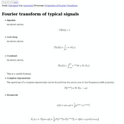
Complex exponential The spectrum of a complex exponential can be found from the above due to the frequency shift property: Sinusoids Similarly, we have Exponential decay - right-sided Exponential decay - left-sided Due to the time reversal property, we also have (for ): or Exponential decay - two-sided As the two-sided exponential decay is the sum of the right and left-sided exponential decays, its spectrum of is the sum of their spectra due to linearity: Comb function The comb function is defined as Its Fourier series coefficient is: and its spectrum is: We see that the spectrum of an impulse train with time interval is also an impulse train with frequency interval . Wireless Emergency Alert system goes live this month, delivers location-based SMS warnings. A Simple Hit Counter. Share This tutorial will show you how to build a simple hit counter.

It does not use any sql or databases and stores the hits in a text file. Al you need to create for this script is your asp file and a text file. In the text file, simply enter the number 0 and save it in the same directory as count.txt. Take a look at the basic source code. <% Response.Expires= -1 Response.AddHeader “Cache-Control”, “no-cache” Response.AddHeader “Pragma”, “no-cache” %> if Session(“ct”) = “” then fp = Server.MapPath(“db\count.txt”) Set fs = CreateObject(“Scripting.FileSystemObject”) Set a = fs.OpenTextFile(fp) ct = Clng(a.ReadLine) ct = ct + 1 Session(“ct”) = ct. Chapter 3: IIR filters - Digital Filter Design. 3.1 Introduction IIR filters are digital filters with infinite impulse response.
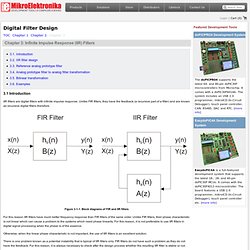
Unlike FIR filters, they have the feedback (a recursive part of a filter) and are known as recursive digital filters therefore. Figure 3-1-1. Block diagrams of FIR and IIR filters For this reason IIR filters have much better frequency response than FIR filters of the same order. Otherwise, when the linear phase characteristic is not important, the use of IIR filters is an excellent solution. There is one problem known as a potential instability that is typical of IIR filters only. IIR filters can be designed using different methods. This book describes the design method using reference analog prototype filter. Tratamiento Digital de Señal.
Chebyshev filter. Because of the passband ripple inherent in Chebyshev filters, the ones that have a smoother response in the passband but a more irregular response in the stopband are preferred for some applications.
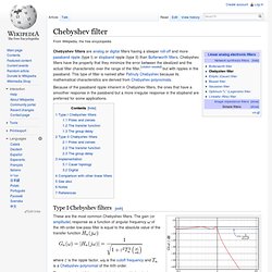
Type I Chebyshev filters[edit] The frequency response of a fourth-order type I Chebyshev low-pass filter with These are the most common Chebyshev filters. The gain (or amplitude) response as a function of angular frequency of the nth-order low-pass filter is equal to the absolute value of the transfer function where.