
Clear View Training. An Introduction to Model-Based Systems Engineering (MBSE) One area of concern within complex systems is cybersecurity.
The SEI CERT Division has begun researching how MBSE can be used to mitigate security risks early in the system-development process so that systems are secure by design, in contrast to the common practice of adding security features later in the development process. Capturing system attributes in models enables systems engineers to perform threat-modeling analysis of the system early and incorporate mitigation strategies into the system design, thereby reducing the system's overall security-related risks.
MBSE in a digital-modeling environment provides advantages that document-based systems engineering cannot provide. For example, in a document-based approach, many documents are generated by different authors to capture the system's design from various stakeholder views, such as system behavior, software, hardware, safety, security, or other disciplines. MBSE is a multidisciplinary and multifaceted endeavor. The Albers Group and Sodius Corp. Announce Partnership to Accelerate Model-Based Systems Engineering (MBSE) Transformation for Defense and Aerospace Markets.
[May 16, 2019] [MCKINNEY, TX] The Albers Group (www.thealbersgroup.com), a Certified Service-Disabled Veteran-Owned and leading US Department of Defense service provider for accelerating the adoption of model-based systems engineering (MBSE), today announces a partnership with Sodius Corp.
(www.sodius.com) to expand The Albers Group's ability to help its customers navigate the MBSE transformation. Conjugation Considered Harmful! – Model Based Systems Engineering. A post by guest author Axel Scheithauer: SysML is based on the UML, and I think that was a good choice.
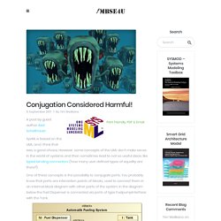
However, some concepts of the UML don’t make sense in the world of systems and then sometimes lead to not so useful ideas, like typed binding connectors (how many user defined types of equality are there?). One of these concepts is the possibility to conjugate ports. You probably know that ports are interaction points of blocks, used to connect them in an internal block diagram with other parts of the system.
In the diagram below the Fuel Dispenser is connected via ports of type FuelpumpInterface with the Tank. Ports have types and these are used to determine, whether it makes sense to connect two ports. So far so good. Modeling support for SysML 1.3 ports. Introducing Model Based Systems Engineering into an Existing/Legacy/Maintenance Project - 321 Gang. Methodologists have devised many workflows for building Systems Engineering models.
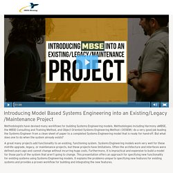
Methodologies including Harmony aMBSE, the MBSE Consulting and Training Method, and Object Oriented Systems Engineering Method (OOSEM) do a very good job leading the Systems Engineer from a clean sheet of paper to a completed Systems Engineering model that is ready for hand-off. But what does one to do when the system already exists? A great many projects add functionality to an existing, functioning system. Systems Engineering models work very well for these mid-life upgrade, legacy, or maintenance projects, but these projects have limitations. Vbauer/lein-plantuml: A Leiningen plugin for generating UML diagrams using PlantUML. Clojure - AtlanMod. System of Systems Engineering: Part II - Overcoming the Challenges.
My previous post titled “System of Systems Engineering: Part I – Challenges” discussed the challenges organizations face with complex System of Systems (SOS) engineering programs.
In this post, I will discuss a potential solution for these challenges by leveraging the IBM Rational Collaborative Lifecycle Management (CLM). This post is based on a paper I previously written about four years ago when I was part of the IBM Software Group covering the Rational solutions. Therefore, it is biased towards the IBM offerings in the software delivery space. System of Systems Engineering: Part I - Challenges. This post is based on a paper titled System of Systems Engineering I’ve written about four years ago.
It provides a clearer understanding of the development challenges. TTool - An open-source UML and SysML toolkit. MARTE References. (Please provide any related MARTE tool that you would like to post to this site to the site coordinator: sebastien.gerard[at]cea.fr)
Architecture Analysis with AADL. AbstractSafety-critical systems, such as those used in avionics and the medical and aerospace domains, are becoming increasingly reliant on software.
Malfunctions in these systems can have significant consequences, including mission failure and loss of life. As a result, they must be designed, verified, and validated carefully to ensure that they comply with system specifications and requirements. A car contains many electronic control units (ECUs)—today’s standard vehicles can contain up to 30 ECUs—that communicate to control systems such as airbag deployment, antilock brakes, and power steering. What’s new in SysML 1.4 – SysML Diagram Interchange. The Diagram Definition (DD – previously known as Diagram Interchange (DI)) is a format to exchange diagram data between tools.
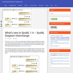
The data about diagrams is separated from the data about the model information. The interchange format for the model data is XMI (XML Metamodel Interchange; see XMI specification page). The following figure depicts the whole picture of the SysML Diagram Interchange architecture. As well as SysML is an extension of UML, the SysML Diagram Interchange is an extension of the UML Diagram Interchange. Integrating Rational Software Architect with Rational Team Concert. Most software development organizations in systems and enterprise areas realize the benefits of Model-Driven Development (MDD) and Unified Modeling Language (UML) and take advantage of them by using the IBM® Rational® Software Architect family of products.
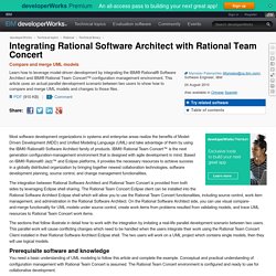
IBM® Rational Team Concert™ is the next generation configuration-management environment that is designed with agile development in mind. Based on IBM® Rational® Jazz™ and Eclipse platforms, it provides the necessary resources to achieve success in a globally distributed organization by bringing together newest collaboration technologies, software development planning, source control, and change management functionalities. The integration between Rational Software Architect and Rational Team Concert is provided from both sides by leveraging Eclipse shell sharing. The sections that follow illustrate in detail how to work with the integration by imitating a real-life parallel development scenario between two users. IBM Rational Architecture Management Software model structure guidelines: Part 1. Fundamentals. About this article This article, Part 1 of a four-part series, lays the foundation for the other articles.
The other articles offer guidelines for modeling according to particular process styles, and this one establishes the concepts and terminology that will be used throughout the series. This article also focuses on considerations of structuring models to support team modeling efforts. Those considerations should inform your thinking regardless of what specific modeling style you choose to adopt.
Collaborative modeling and metamodeling. Systemarchitect.info. How to share DoDAF2 data with Rational System Architect. Develop and deploy your nextapp on the IBM Bluemixcloud platform. Start your free trial Overview The need to share enterprise architecture data has brought about various data interchange approaches over many years, some based on industry standards while most depended on ad hoc methods. The approaches required some amount of work to implement across the various modeling tools, other tools and databases.
ModelBus - Welcome To ModelBus.org. Download?doi=10.1.1.138. Bringing together Systems Engineering and the Semantic Web. Systems Engineering (SE) is a vast discipline that includes many sub-disciplines. The International Council on Systems Engineering (INCOSE) defines Systems Engineering as: “<.. > an interdisciplinary approach and means to enable the realization of successful systems. It focuses on defining customer needs and required functionality early in the development cycle, documenting requirements, then proceeding with design synthesis and system validation while considering the complete problem: Systems Engineering integrates all the disciplines and specialty groups into a team effort forming a structured development process that proceeds from concept to production to operation.
2006-03-16-Frontiers2006-Burkhart-2. PdfrV7esTvCnf. Owled2009_submission_8. 0910-jenkins. 13640_PalmerThursday. 13640_PalmerThursday. Ontologies-mbse-usc-2010-03-10. State_Analysis_Ontology _in_SysML. Rouquette. Introduction to UML2 Profiles. Copyright 2004, 2008 International Business Machines Corp. Summary This article describes how to work with profiles using the UML2 plug-ins for Eclipse. In particular, it gives an overview of how to create and apply profiles (and their contents) both programmatically and by using the sample UML editor Kenn Hussey, IBM (Updated: for Eclipse 3.4; James Bruck) Prerequisites To start using UML2 (and to follow along with the example in this article), you must have Eclipse 3.4, EMF 2.4, and UML2 2.2 installed.
You can either download the zips individually and expand them out or follow the steps below: Fetch.php?media=mbse:10.1007_s10472-011-9267-5. Tim Weilkiens Blog about Model Based Systems Engineering (MBSE) INCOSE-OMGSysML-Tutorial-Final-090901.pdf (Objet application/pdf) What’s new in SysML 1.4 – Constraining decompositions. The fourth part of the blogpost series about the changes in SysML 1.4 presents the new concept to constrain a decomposition hierarchy. The following figure shows a simple product tree of a drone subsystem (DS) for a forest fire detection system (FFDS).
It is the sample system I’ve also used in some previous posts. Product tree of a drone subsystem for a forest fire detection system (click to enlarge) The structure allows different configurations of drone subsystem instances due to the multiplicitiy of the camera and the heat sensor and generalization of the camera. For instance drones with 2 standard FFDS cameras and no heat sensor or 1 highend FFDS camera and 1 heat sensor and so on.