

Understanding Spread Spectrum Radios, PCM Radios, FM Radios, and AM radios. 2.4 GHz spread spectrum radios have taken the RC world by storm.
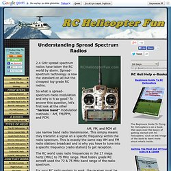
Spread-spectrum technology is now the standard on all but the cheapest toy grade RC radios. So what is spread-spectrum-radio modulation and why is it so good? To answer this question, let’s first look at the other ”narrow band” modulation methods – AM, FM/PPM, and PCM. AM, FM, and PCM all use narrow band radio transmission. This simply means they transmit a signal on a specific frequency within the radio spectrum. The RC world uses radio frequencies in the 27 mega hertz (MHz) to 75 MHz range. For your RC radio system to work, the receiver must be tuned into the exact same frequency as the RC radio, this allows several models to be flying at once provided they are all on different frequencies within the allowed band range. With only a few dozen channels or so available, it is very important that only one person be transmitting on a specific channel at a time.
ABCs of Spread Spectrum - A Technology Introduction and Tutorial. Introduction to Spread Spectrum by Randy Roberts, Director of RF/Spread Spectrum Consulting (Retired) Over the last eight or nine years a new commercial marketplace has been emerging.

Called spread spectrum, this field covers the art of secure digital communications that is now being exploited for commercial and industrial purposes. In the next several years hardly anyone will escape being involved, in some way, with spread spectrum communications. Applications for commercial spread spectrum range from "wireless" LAN's (computer to computer local area networks), to integrated bar code scanner/palmtop computer/radio modem devices for warehousing, to digital dispatch, to digital cellular telephone communications, to "information society" city/area/state or country wide networks for passing faxes, computer data, email, or multimedia data. MSP430 LaunchPad PushButton.
By Aldo Briano This module configures a pushbutton to turn on and off an LED.
By pressing the button, the LED turns on. When the button is released, the LED turns off. Interrupts are used to read the input from the digital port. Two examples are explained, using the onboard button and LED of the LaunchPad kit, and interfacing external hardware components to the LaunchPad. Get external components. 1 Resistance: 33KOhm 1 Capacitor: 470nF External switch / button Small breadboard and jumper cablesCreate new project in CCS and copy/paste code Build circuit. MSP430F5438A Running UART-03 Example Code get error "An internal error has occurred, Argument cannot be null" - MSP430 Ultra-Low Power 16-bit Microcontroller Forum - MSP430™16-bit Ultra-Low Power MCUs. Wing NgP3IN = 0x08; // P3.5 RXD input should change to P3IN = 0x20; // P3.5 RXD input ????
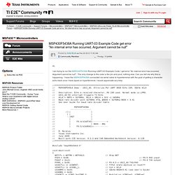
Often, people forget to change the comments when changing the code. But PxIN is read-only, so writing to it makes no sense at all. No matter which value.And P3OUT doesn't need to be set, since the USCI controls the direction and PxOUT is ignored if the pins are under USCI control. However, this does not affect functionality at all. The problem was a compiler error. But nwo that you mention it, it may be that the compiler somehw knows that P2IN is read-only and chokes on teh attempt to write something to it.Strange, as you can actually write to P3IN, it just has no effect. _____________________________________Before posting bug reports or ask for help, do at least quick scan over this article. MSP430™16-bit Ultra-Low Power MCUs - 5 Series - MSP430F5438A.
View topic - GPS and MSP430. Hello!
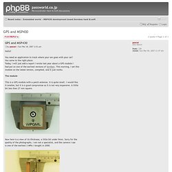
You need an application to track where your son goes with your car? You came to the right place. Today, I will just add a report I wrote last year about a GPS module I had put on one of the earliest versions of Soroban. This morning, I set this module on the latest version, compiled, and it just works. The module This is a GPS module with a patch antenna.
Now here is a view of its thickness, a little bit under 9mm. The platformThis time (surprise?) Wiring the module on Soroban Before wiring, I had to punch a hole to leave some room for the 3 antenna pins that are off-pitch. Www.control.aau.dk/~bisgaard/teaching/d3/dap/dap-litterature/EW430_UserGuide.pdf. Direct-sequence spread spectrum. Features[edit] Transmission method[edit] Direct-sequence spread-spectrum transmissions multiply the data being transmitted by a "noise" signal.
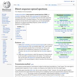
This noise signal is a pseudorandom sequence of 1 and −1 values, at a frequency much higher than that of the original signal. The resulting signal resembles white noise, like an audio recording of "static". However, this noise-like signal is used to exactly reconstruct the original data at the receiving end, by multiplying it by the same pseudorandom sequence (because 1 × 1 = 1, and −1 × −1 = 1). The resulting effect of enhancing signal to noise ratio on the channel is called process gain. If an undesired transmitter transmits on the same channel but with a different PN sequence (or no sequence at all), the de-spreading process has reduced processing gain for that signal. Benefits[edit] Uses[edit] See also[edit] References[edit] External links[edit]