0-40Mhz, Sine wave generator for $25. - All. In the setup code you will just need to define what pins you have used for what job between the DDS board and the Arduino.
#define data_pin 12 #define load_pin A5 #define clock_pin A4 #define clock_hz 120000000LL dds ddschip(DDS9850, data_pin, load_pin, clock_pin, clock_hz); This sets my dds up with its 120mhz onboard crystal. I am substituting the pin numbers with words to make it easier to understand. For example the word data_pin would be replaced everywhere it is found at compile time with the number 12. this is what the #define command does Now the chip pins have been defined, we can just use the ddschip.setfrequency(Frequency); command to set the frequency to any frequency we desire, within the capabilities of the device. I figured that i would use the up and down buttons to raise or lower the frequency.
I decide to use the left and right buttons to cycle the amount the frequency would increment on raising or lowering. Technoblogy - Waveform Generation using an ATtiny85. 5th October 2014 This article describes how to generate different waveform shapes using Direct Digital Synthesis or DDS on an ATtiny85.

This program forms the basis for a simple synthesiser that I plan to describe in a later article. Introduction The simplest way to play tunes on an Arduino, or other AVR chip, is to use one of the timer/counters to divide the clock frequency by a divisor corresponding to the note you want to play. The smaller the divisor, the higher the frequency. Resistor ladder - Wikipedia.
Lab 2d Sine Wave Generator. GitHub - skywodd/attiny_software_dac_single: Single output software DAC for ATtiny 25 / 45 / 85. [ATtiny] Générateur de signaux DDS (DAC software) Bonjour tout le monde !
![[ATtiny] Générateur de signaux DDS (DAC software)](http://cdn.pearltrees.com/s/pic/th/generateur-signaux-software-141202340)
Aujourd’hui je continue sur ma lancée avec un nouvelle article sur la conversion numérique -> analogique. Dans mon dernier article je vous avez montrez comment utiliser un MCP4725 pour générer un signal analogique. Aujourd’hui on passent au cran au dessus en générant un signal analogique SANS aucun CI spécialisé ! MER IL EST FOU ! Comment un tel exploit est-il possible !? Le principe utilisé dans cet article ce résume en trois lettres : DDS aka « Direct digital synthesizer ». Selon wikipedia voila ce que DDS signifie :Direct Digital Synthesizer (DDS) is a type of frequency synthesizer used for creating arbitrary waveforms from a single, fixed-frequency reference clock. En gros en utilisant une fréquence de référence fixe, on peut générer un signal totalement arbitraire selon nos envies.
Ok mais … COMMENT !? Le principe est simple, beaucoup de micro-contrôleurs possède un générateur de signal PWM. Le principe : Abat la théorie, vive la pratique ! Le résultat : Arduino simple signal generator. Using a arduino and some resistor to work as a 8bit DAC, so we can make some waveform form it , build a Arduino simple signal generator. what you need just a Arduino, a protoshild and some resistor.
Now we make a Arduino Signal Generator that build on Protoshield. There is a simple signal generator kit in our store, it selling well ,but it’s source is not released so we can’t modify it for more DIY. The principle of this signal generator is like a 8bit DAC, so just need some resistor we can build it on Arduino . We make a prototype on the Arduino prototype shield : The schematic is very sample .Note that one thing, the higher precision resistors you used , the better effect.
So the Arduino signal generator kit include : Arduino proto shield kit 1 10k resistors 9 20k resistors 8 Button 1 How to write the code ? Unsigned char sin_tab [256] = { Of cause , it can be divided it into 512,1024, the more subdivision the better effect. void setup() { DDRD =0xFF; } Comment aborder la DDS.
La DDS ( Direct Digital Synthesis ) appartient à une technologie permettant de construire un générateur Haute Fréquence couvrant la bande des Ondes Courtes de 1 à 30 MHz sans trous en générant un signal sinusoïdal stable comme un roc.

Arduino Function Generator (Part 3) – Auctoris. In my previous posts in this series I looked at a couple of ways to use an Arduino to generate analogue waveforms.
In this third part I look at a much simpler, IC-based digital to analog (DAC) circuit to provide the waveforms, and look at ways of changing the frequency of the output. Let’s start with the new circuit. In part two of this series, I used an R-2R ladder resistor network built from discrete components. This time I’m going to use the same concept (a R-2R ladder), but rather than building it from discrete resistors, I’m going to use a pre-built IC. In this case I used the TI TLC7226, but the same principles will apply to most DACs. The circuit is very simple – and can basically be designed by looking at the data sheet. Given that we’re only interested in one output – we can simply pull both of the address bits (pins 16 & 17 – A0 & A1) high to select (in this case) output D. The code is almost identical to the code we used previously. So, what about changing the frequency? Arduino Function Generator (Part 2) – Auctoris.
Last time, we looked at some Arduino code that we could use to generate some square waves.
The problem with the setup we’ve been looking at so far, is that we can only produce signals of one amplitude – equivalent to the HIGH logic level. In order to be able to produce any other waveforms we’ll need to be able to produce a variety of different output voltages. Although the PWM method we looked at last time gives us a way to do this, it’s not suitable for producing variable waveforms – as it’s time-based. Arduino Waveform Generator. Waveform generators (also called function generators) are useful for testing and debugging circuits.
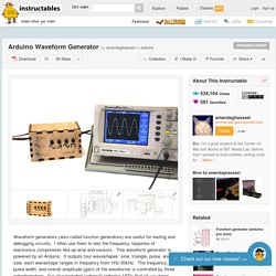
I often use them to test the frequency response of electronics components like op amp and sensors. This waveform generator is powered by an Arduino. It outputs four waveshapes: sine, triangle, pulse, and saw, each waveshape ranges in frequency from 1Hz-50kHz. The frequency, pulse width, and overall amplitude (gain) of the waveforms is controlled by three potentiometers.