
How to build your own LED Color Organ. Цветомузыка на 4 канала своими руками. Светомузыка на 4 канала своими руками-схема Еще одна схема устройства присланная Айдаром Галимовым.
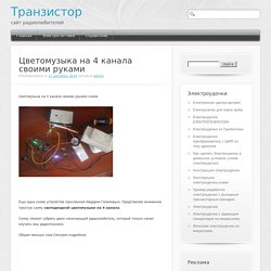
Представляю вниманию простую схему светодиодной цветомузыки на 4 канала. Схему сможет собрать даже начинающий радиолюбитель, который только начал изучать азы радиотехнике. Общем меньше слов.Смотрим подробнее Схема устройства: Как видно, в схеме не использованы микросхемы.Что упрощает сборку. Video and Write-Up: Final Prototype of Audio Spectrum Analyzer Using Arduino and MSGEQ7. Demo video of the Audio Spectrum Analyzer using the MSGEQ7 and fourteen LEDs.
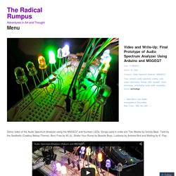
Songs used in order are Two Weeks by Grizzly Bear, Tank by the Seatbelts (Cowboy Bebop Theme), Born Free by M.I.A., Shake Your Rump by Beastie Boys, Lusitania by Andrew Bird and Waiting by K. Flay. As a quick review: The MSGEQ7 is a (from the data sheet) “seven band graphic equalizer IC…that divides the audio spectrum into seven bands, 63Hz, 160Hz, 400Hz, 1kHz, 2.5kHz, 6.25kHz and 16kHz. The seven frequencies are peak detected and multiplexed to the output to provide a DC representation of the amplitude of each band” ( After playing around with both the code and circuit, I now have the final prototype before I look into permanent housing for it. Again, basis for project is coming from CMiYC’s original code: Full circuit view The first change that I started with was adding an LED for each of the seven bands identified by the MSGEQ7.
On the left: original code from CMiYC Labs. Lights in action Pink LEDs! Like this: Arduino spectrum analyzer / DJ set. Educational BoosterPack 8 bit FFT spectrum analyzer. Как подключить драйвер светодиодов tlc5940 к Arduino. Из статьи вы узнаете, как подключить светодиодный драйвер TLC5940 к Ардуино, как подключить несколько драйверов в цепочке и как управлять ими с помощью библиотеки tlc5940.
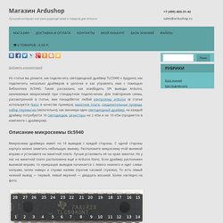
Также рассказано, как освободить SPI выводы Arduino, занимаемые микросхемой при стандартном подключении. Для повторения схемы, рассмотренной в статье, вам понадобятся: любой контроллер arduino (в статье используется Nano в качестве примера), макетная плата, соединительные провода, набор перемычек (желательно), как минимум один светодиодный драйвер, на каждый драйвер потребуется 16 светодиодов, резисторы на 2 кОм и на 10 кОм (продаются в комплекте с драйвером). Микросхема драйвера имеет по 14 выводов с каждой стороны. С одной стороны корпуса можно заметить небольшую выемку. Расположите микросхему этой выемкой вправо и установите на макетной плате. Драйвер светодиодов TLC5940 Подключите выводы драйвера к arduino в следующем порядке: Подключение самого драйвера окончено.
How to Control a Ton of RGB LEDs with Arduino & TLC5940. How To RGB 8x8x8 LED CUBE - The BUILD! Apartment Light Show: Arduino Style. Arduino spectrum analyser with ht1632c part 1. Spectrum Analyzer with Arduino. Sparkfun Spectrum Shield Audio Equalizer LCD. Spectrum Analyzer, Arduino project with FFT algorithm -Use Arduino for Projects. The basic idea was to create color organ / spectrum analyzer on arduino board, trying to minimize quantity of external components, like analog filters, LED display drivers, etc.
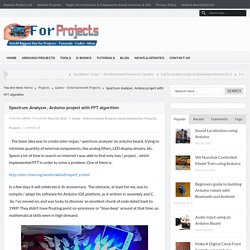
Spend a lot of time in search on internet I was able to find only two ! Project , which implemented FFT in order to solve a problem. One of them is: in a few days it will celebrate 6-th anniversary. The obstacle, at least for me, was to compile / adapt his software for Arduino IDE platform, as it written in assembly and C. FFT algorithm could find application in wide variety of projects, for example, musical note recognition, voice recognition, sound localization etc. D = 1 / (14.6 * 10^-3) = ~ 70 Hz. Sum up first 10 fx bins, I’m getting 35 <—> 735 Hz frequency range for red LED’s, from 11-th to 20-th consequently provides me 735 <—> 1435 Hz for green LED’s, and from 21-st to 31-st 1435 <—> 2170 Hz range for blue LED’s.
Now hardware part. Holding Focus: Arduino Realtime Audio Spectrum Analyzer with Video out! Once again, I decided to put the old travel DVD player's screen to good use by using as an output device for the Arduino.
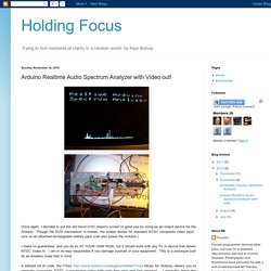
Though the DVD mechanism is broken, the screen allows for standard NTSC composite video input.. runs on an attached rechargeable battery pack (can also power the Arduino.) I make no guarantees, and you do so AT YOUR OWN RISK, but it should work with any TV or device that allows NTSC Video In. I am in no way responsible if you damage yourself or your equipment. This is a prototype built by an amateur, keep that in mind. A brilliant bit of code, the TVout library for Arduino, allows you to generate composite NTSC monochrome video with only two pins and two resistors. The other piece of the puzzle is collecting and processing audio, so we have something to display on our little display. The first piece- data collection- is fairly standard. Лазерное шоу, управляемое через LPT / Хабрахабр. Я раскажу Вам как можно сделать лазерное шоу управляемое через порт LPT.
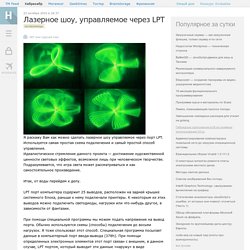
Используется самая простая схема подключения и самый простой способ управления. Идеалистическое стремление данного проекта — достижение художественной ценности световых эффектов, возможное лишь при человеческом творчестве. Подразумевается, что игра света может рассматриваться и как самостоятельное произведение. Спектроанализатор с выводом в программу на ПК. Spectrum Analyzer with Arduino.